Supercharge Your Innovation With Domain-Expert AI Agents!

Method and apparatus for blow molding receptacles

A technology of blow molding, containers, applied in the field of container equipment, capable of solving the problems of material waste, cost increase, unsatisfactory waste volume or production start delay

Inactive Publication Date: 2011-06-29
KHS CORPOPLAST GMBH & CO KG
View PDF8 Cites 8 Cited by
  • Summary
  • Abstract
  • Description
  • Claims
  • Application Information

AI Technical Summary

Problems solved by technology

[0015] The amount of scrap or delays in the start of production due to the described mode of operation of the blow molding machine are considered unsatisfactory and ultimately lead to increased costs due to material waste or unavailable production time

Method used


Image

  • Method and apparatus for blow molding receptacles
  • Method and apparatus for blow molding receptacles
  • Method and apparatus for blow molding receptacles

Examples


Embodiment Construction

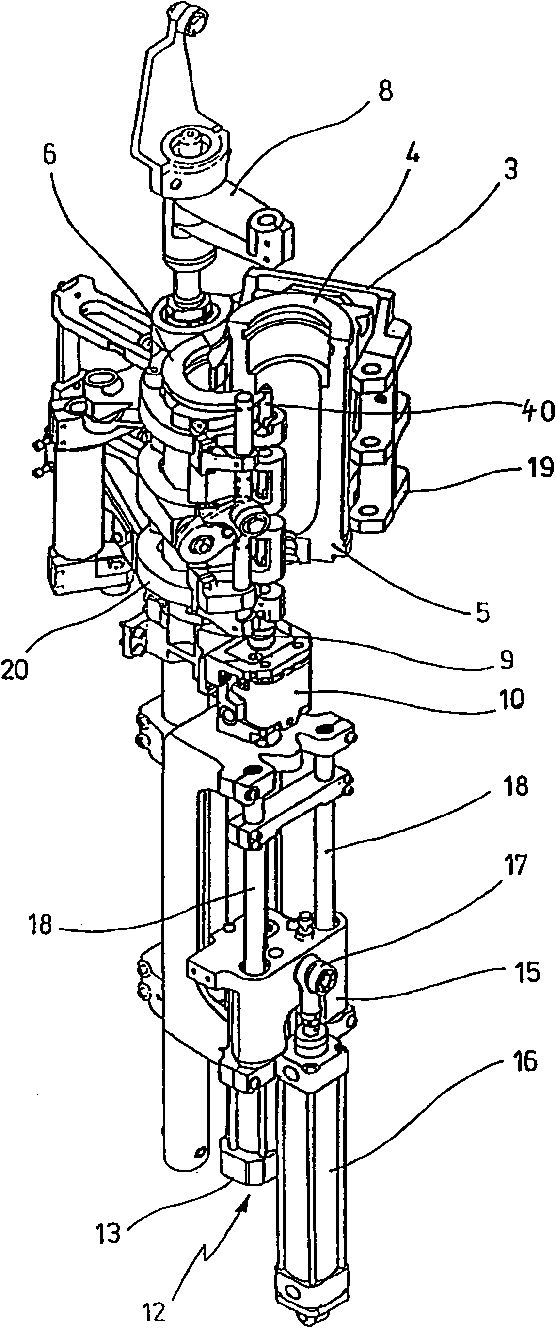
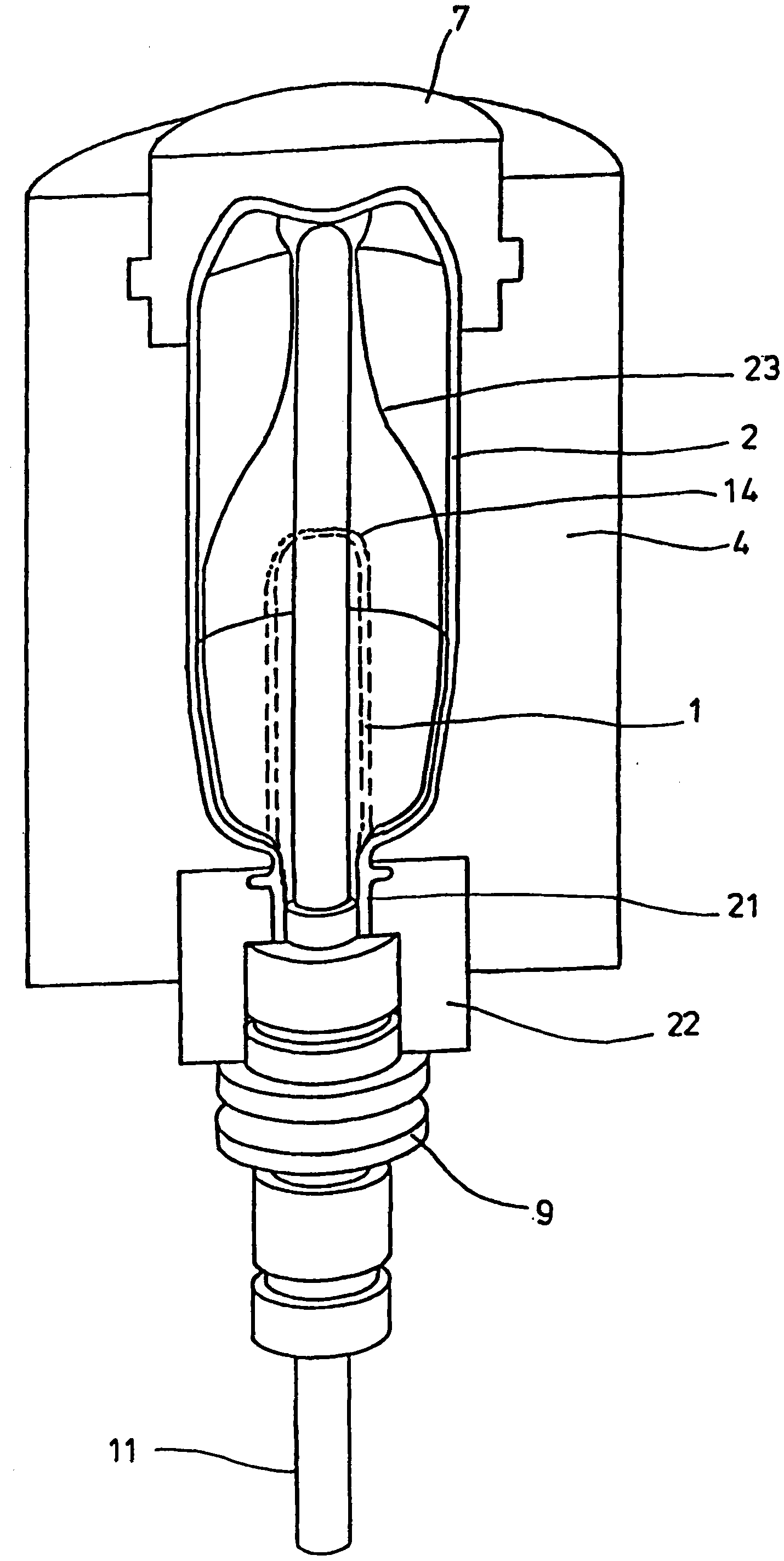
[0035] exist figure 1 and 2 The schematic structure of a device for forming preforms 1 into containers 2 is shown in .

[0036] The plant for shaping the container 2 basically comprises a blow molding station 3 provided with a blow mold 4 into which the preform 1 can be inserted. The preform 1 can be an injection molded part made of polyethylene terephthalate. In order to allow the introduction of the preform 1 into the blow mold 4 and to allow the removal of the finished container 2, the blow mold 4 consists of mold halves 5, 6 and a bottom part 7 which can be lifted by a The device 8 is positioned. The preforms 1 can be held in the region of the blow molding station 3 by a transport mandrel 9 which, together with the preforms 1 , passes through several processing stations within the installation. However, it is also possible to insert the preform 1 directly into the blow mold 4 , for example by means of clamps or another operating mechanism.

[0037] To allow the introd...


PUM


Abstract

Disclosed are a method and an apparatus for blow molding receptacles. A parison made of a thermoplastic material is first subjected to a thermal conditioning process in the zone of a heating section along a path of travel. The parison is then shaped into the receptacle within a blow mold (4) by applying blowing pressure. The heating element is connected to a heat controller which has controller characteristics in such a way that the heating elements are operated at a heating capacity that is substantially constant over time. The stretching device (11, 12, 13) is connected to a stretching controller which has controller characteristics in such a way that a stretching rate immediately after starting the device is different from a stretching rate during a production phase a certain period of time after starting the device.

Description

technical field [0001] The invention relates to a method for blow molding containers, in which a preform made of thermoplastic material is stretched inside a blow mold after thermal conditioning along a conveying path in the region of a heating section and blown Shaped into containers by plastic pressure. [0002] Furthermore, the invention relates to a plant for the blow molding of containers made of thermoplastic material, which has at least one heating section arranged along a conveying path of the preforms and a blowing station with a blowing mould. , wherein the heating section has at least one heating element and a stretching device is arranged in the region of the blow molding station. Background technique [0003] When forming containers by means of blow molding pressure, preforms made of thermoplastic material, for example PET (polyethylene terephthalate), are fed to different workstation. Typically, such a blow molding machine has a heating device and a blow mol...

Claims


Application Information

Patent Timeline
IPC IPC(8): B29C49/78B29C49/12B29C49/64
CPCB29C2049/4889B29C49/6454B29C2049/1271B29C49/36B29C49/78B29C2049/1257B29C49/6445B29C33/26B29C49/12B29C49/6409B29C49/06B29C49/1222B29C49/1229B29C49/42073B29C49/42085B29C49/42095B29C49/42407B29C49/561B29C2949/0715B29C2049/023B29C49/6427B29C49/6435B29C49/6835B29C2049/7831B29C2049/7832B29C2049/7871B29C2049/7879B29C2049/78805
Inventor F·黑森东克斯K-H·巴尔考M·马蒂森R·鲍姆加特F·莱温M·利岑贝格M·林克
Owner KHS CORPOPLAST GMBH & CO KG
Features
  • R&D
  • Intellectual Property
  • Life Sciences
  • Materials
  • Tech Scout
  • Unparalleled Data Quality
  • Higher Quality Content
  • 60% Fewer Hallucinations
Learn More