Automatic analyzing device

An automatic analysis device and action technology, applied to the analysis of materials, instruments, etc., can solve the problems of reduced processing capacity, unnegligible decrease in sample concentration, increase in cleaning times of dispensing nozzles, etc., and achieve the effect of preventing concentration changes

Inactive Publication Date: 2011-06-29
HITACHI HIGH-TECH CORP
View PDF6 Cites 6 Cited by
  • Summary
  • Abstract
  • Description
  • Claims
  • Application Information

AI Technical Summary

Problems solved by technology

Since the dispensing nozzle needs to be cleaned every time a dispensing operation is performed, the number of cleanings of the dispensing nozzle increases, and the cleaning liquid adhering to the outer wall of the dispensing nozzle is brought into the sample, so that the concentration of the sample cannot be ignored reduce
[0009] Patent Document 1 describes a method of removing cleaning liquid droplets adhering to the outer wall of the dispensing nozzle by vacuum suction, but since the suction operation of the outer wall of the nozzle is added after cleaning the dispensing nozzle, the processing capacity may be reduced.

Method used


Image

  • Automatic analyzing device
  • Automatic analyzing device
  • Automatic analyzing device

Examples


Embodiment 1

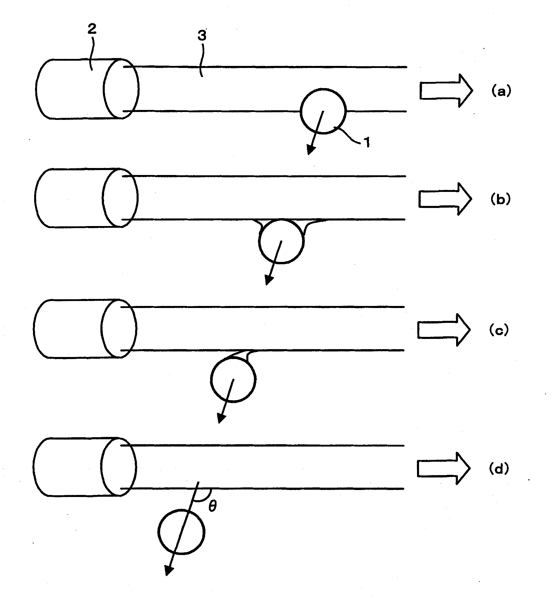
[0036] figure 1 A schematic diagram showing the cleaning operation of the dispensing nozzle using the jet effect. A dispensing nozzle with an outer diameter of 0.25 mm sucks the sample after descending into the sample container to detect the liquid level of the sample. Then, the dispensing nozzle 1 moves to the front of the cleaning nozzle 2 of the cleaning tank. Next, the cleaning liquid flow 3 is discharged from the cleaning nozzle 2 with an inner diameter of 2.5 mm at a flow rate of 1.5 m / s in a direction of 60° downward from the horizontal, and the excess detection fluid attached to the outer wall of the dispensing nozzle 1 is cleaned in the cleaning liquid flow. body. The cleaning liquid flow is preferably a smooth flow with little pulsation and always flowing through a fixed position.

[0037] At this time, the dispensing nozzle 1 moves across the cleaning liquid flow 3 and moves on a plane where the position leaving the cleaning liquid flow is closer to the opening o...

Embodiment 2

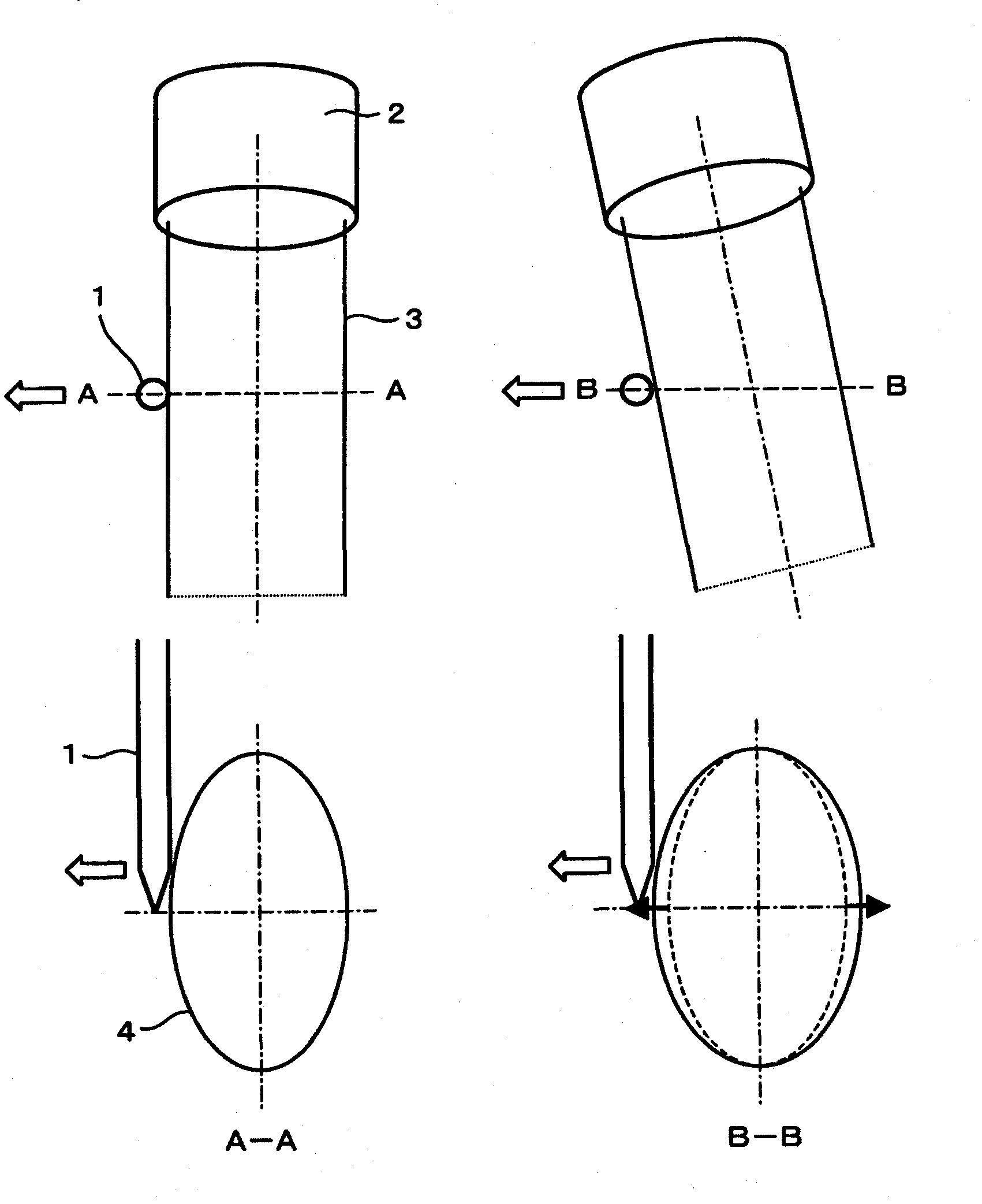
[0041] image 3 A water flow cross section is shown when the dispensing nozzle 1 passes through the cleaning liquid flow 3 discharged from the cleaning nozzle 2 having a discharge port diameter of 2.5 mm in a direction 60° downward from the horizontal. In the case of inter-item cleaning for cleaning the front end of the dispensing nozzle, if the dispensing nozzle 1 only crosses the upper half of the section of the cleaning liquid flow 3 and moves horizontally, the front end of the dispensing nozzle finally moves from the upper half of the elliptical section Disengage (A-A). Since the tip of the dispensing nozzle is sharp, the surface area is small and the force to hold the water droplet is small. Therefore, when the tip of the dispensing nozzle is finally detached from the cleaning liquid flow 3, the amount of adhesion of the cleaning liquid flow 3 to the outer wall of the dispensing nozzle can be reduced.

[0042] In addition, the traveling direction of the dispensing nozzl...

Embodiment 3

[0048] Image 6 Shows a cleaning mechanism that maximizes the spray effect by moving the cleaning liquid flow.

[0049] The cleaning nozzle 2 is connected with an automatic flow switching valve 4 on the connected cleaning liquid pipeline. The cleaning nozzle 2 has a discharge opening diameter of 2.5 mm, and discharges a cleaning liquid flow 3 at 60° downward from the horizontal at a flow velocity of 1.5 m / s. The dispensing nozzle 1 moves toward the cleaning tank and stops at a position about 2.8 mm from the inner upper end of the discharge port of the cleaning nozzle 2 . In the inter-specimen cleaning before starting the analysis, it is necessary to clean the dispensing nozzle 1 as wide as possible, so the automatic flow switching valve 4 is adjusted so that the cleaning liquid flow 3 is discharged as shown by the dotted line, so that the dispensing nozzle is approximately The range of 5mm is in contact with the cleaning solution.

[0050] On the other hand, after aspiratin...


PUM


Abstract

When dispensing operation is conducted plural times from an identical specimen, a rinsing liquid having stuck to the outer wall of a dispensing nozzle rinsed may be brought into a specimen container when the specimen is sucked, thereby to thin the specimen and lower an analyzing precision. The invention provides a rinsing mechanism for an automatic analyzing device, the rinsing range of the outer wall of the dispensing nozzle is changed according to the range, within which the nozzle is blotted. The quantity of the rinsing liquid to stick to the outer wall of the dispensing nozzle is reduced by an ejector effect to act between the dispensing nozzle and a rinsing liquid flow, thereby to prevent the specimen from becoming thinner. The rinsing mechanism decides a discharged state of the rinsing liquid flow by using the liquid level detecting function of the nozzle and the pressure fluctuation detecting function of the inside of a nozzle pipe, so that a highly reliable analysis is realized in an automatically adjustable manner for the proper rinsing range.

Description

technical field [0001] The present invention relates to an automatic analyzer for measuring components to be tested in a sample, and more particularly to an automatic analyzer for cleaning liquid droplets adhering to the outer wall of a nozzle with liquid. Background technique [0002] The automatic analysis device is a device that has the following functions. The sample such as serum obtained by centrifuging blood and the reagent are dispensed into the reaction container by the dispensing mechanism, stirred, and the reagent and serum components are measured by a photometer. The absorbance that changes according to the response of the sample can be used to calculate the concentration of the target component contained in the sample. [0003] In the automatic analysis device, in order to repeat the above-mentioned analysis operation, the inner and outer walls of the dispensing nozzle are regularly cleaned to prevent the sample and other samples from adhering to the inner and o...

Claims


Application Information

Patent Timeline
Patent Type & Authority Applications(China)
IPC IPC(8): G01N35/10
CPCG01N35/1004
Inventor 三岛弘之中泽隆史
Owner HITACHI HIGH-TECH CORP
Why Eureka
Try Eureka