Purification drinking device and control method thereof

A technology of drinking water device and control method, which is applied in the direction of beverage preparation device, chemical instrument and method, separation method, etc. It can solve the problems of lack of heating and cooling functions, difficulty in adding water, and difficult matching, so as to save purchase cost and land occupation Space, easy to take out for cleaning or add water, easy to use and maintain

Inactive Publication Date: 2011-07-06
QINYUAN GRP CO LTD
View PDF5 Cites 7 Cited by
  • Summary
  • Abstract
  • Description
  • Claims
  • Application Information

AI Technical Summary

Problems solved by technology

[0002] The traditional water purifier must be used in conjunction with the water dispenser, and it can be used independently without heating and cooling functions, and the father-son assembly relationship of the bucket inside the bucket and the core inside the bucket used in the structure is extremely unfavorable for cleaning and maintenance
[0003] Since water appliances have not yet formed a unified industry standard, it is difficult for the water puri

Method used


Image

  • Purification drinking device and control method thereof
  • Purification drinking device and control method thereof
  • Purification drinking device and control method thereof

Examples


Embodiment 1

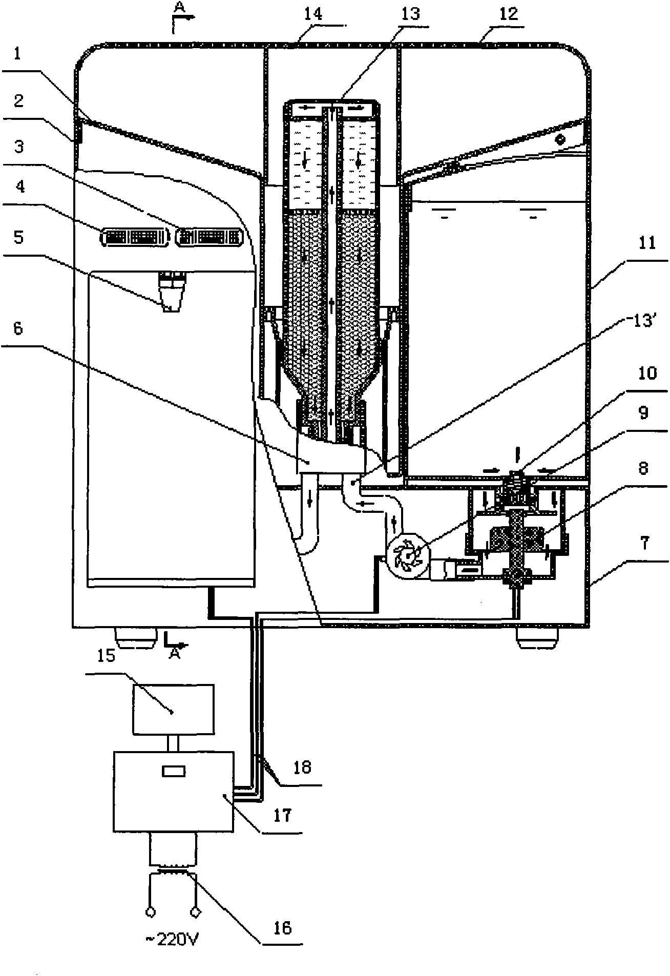
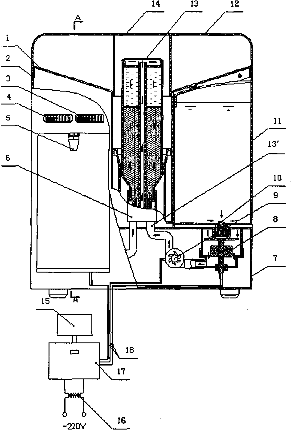
[0038] Such as figure 1 and figure 2 As shown, the drinking water device of the present embodiment comprises: the raw water tank 11, the water pump 9, the filter element 13, the water outlet tap 5 connected in series through the waterway in sequence, to form the clean water supply waterway; and the drinking water system (in this embodiment, the drinking water system is The semiconductor refrigeration system 20) is arranged on the bypass waterway of the water purification waterway between the filter element 13 and the water outlet faucet 5, and the bypass waterway is connected in parallel with the water purification waterway.

[0039] Thereby, the filter element 13 is communicated with the water outlet tap 5 through the parallel water purification waterway and the bypass waterway, the bypass waterway supplies drinking water to the water outlet faucet 5 (clear water after refrigeration here), and the water purification waterway leads to the water outlet faucet 5 Supply clean w...

Embodiment 2

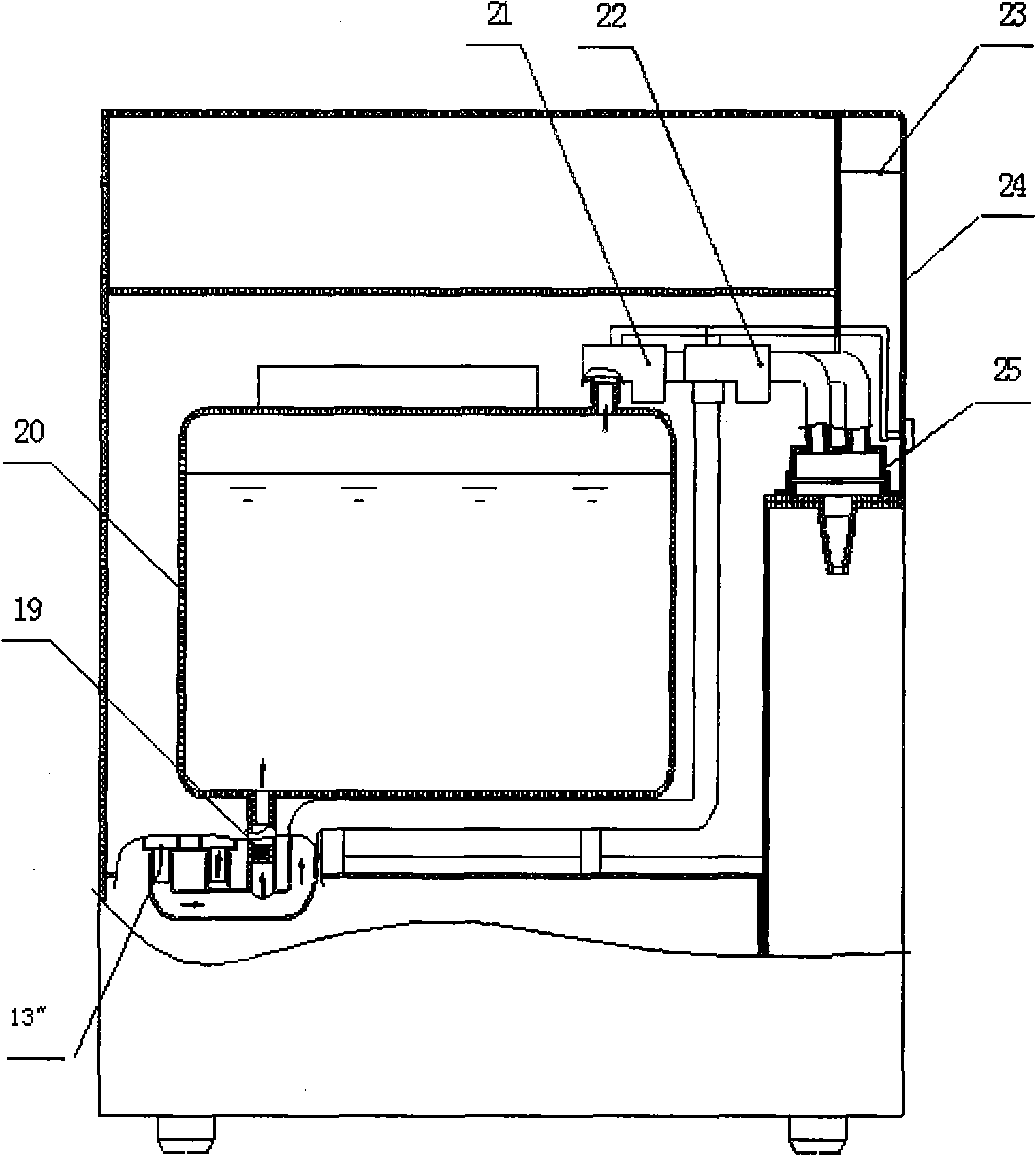
[0051] Figures 3 to 4 The second embodiment of the drinking water purification device of the present invention is shown. The only difference between the second embodiment and the first embodiment is that the first embodiment describes how the drinking water purification device of the present invention realizes the purification + cooling function, while the second embodiment describes It is how the drinking water purification device of the present invention realizes the purification + heating function. In the first embodiment, as long as the semiconductor refrigeration system 20 is replaced with the heating system 20' with a thermal bladder, the first embodiment is the second embodiment, and vice versa, so In the second embodiment, the content other than the difference from the first embodiment will not be described.


PUM


Abstract

The invention discloses a purification drinking device. The device comprises a raw water tank, a water pump, a filter element and a water outlet tap which are sequentially connected in series through water pipes to supply purified water, and a drinking system, wherein the drinking system is arranged on a bypass water pipe of a purified water pipe between the filter element and the water outlet tap, and the bypass water pipe is connected with the purified water pipe in parallel. The invention also provides a method for controlling the purification drinking device. The method comprises the following steps of: pumping water in the raw water tank into the filter element by using the water pump for purification; and pumping out the purified water through any one of two parallel water pipes, wherein one of the two parallel water pipes is provided with the drinking system which refrigerates or heats the purified water, and the other water pipe is the purified water pipe. The purification drinking device not only integrates purification function with drinking function (refrigeration or heating), but also is easy to detach and clean, and convenient for adding water.

Description

technical field [0001] The invention relates to a drinking water purification device and a control method thereof. Background technique [0002] Traditional water purifiers must be used in conjunction with water dispensers. Those that can be used independently do not have heating and cooling functions, and the structurally adopted father-son assembly relationship of a bucket inside a bucket and a core inside the bucket is extremely unfavorable for cleaning and maintenance. [0003] Since the water appliances have not yet formed a unified industry standard, it is difficult for the water purifiers produced by various manufacturers to match the water dispensers produced by other manufacturers, which severely limits the choice of consumers to purchase water purifiers or water dispensers; and The water purifier and water dispenser produced by the same manufacturer also have disadvantages such as incoordination of shape and color, high price, large floor space, and high overall he...

Claims


Application Information

Patent Timeline
IPC IPC(8): B01D24/48B01D24/14B01D35/18
CPCA47J31/605A47J31/54
Inventor 沈选举赵敏捷潘振豪
Owner QINYUAN GRP CO LTD
Why Eureka
Try Eureka