Polishing wheel diameter and polishing force detection method and polishing wheel wear compensating method

A detection method and wear compensation technology, which can be applied to grinding/polishing equipment, parts of grinding machine tools, metal processing equipment, etc., and can solve problems such as lag

Inactive Publication Date: 2011-07-06
BEIHANG UNIV
View PDF4 Cites 22 Cited by
  • Summary
  • Abstract
  • Description
  • Claims
  • Application Information

AI Technical Summary

Problems solved by technology

The above principle is feedback control, there must be a lag

Method used


Image

  • Polishing wheel diameter and polishing force detection method and polishing wheel wear compensating method
  • Polishing wheel diameter and polishing force detection method and polishing wheel wear compensating method
  • Polishing wheel diameter and polishing force detection method and polishing wheel wear compensating method

Examples


Embodiment Construction

[0008] The technical solution of the present invention will be further described below in conjunction with the accompanying drawings.

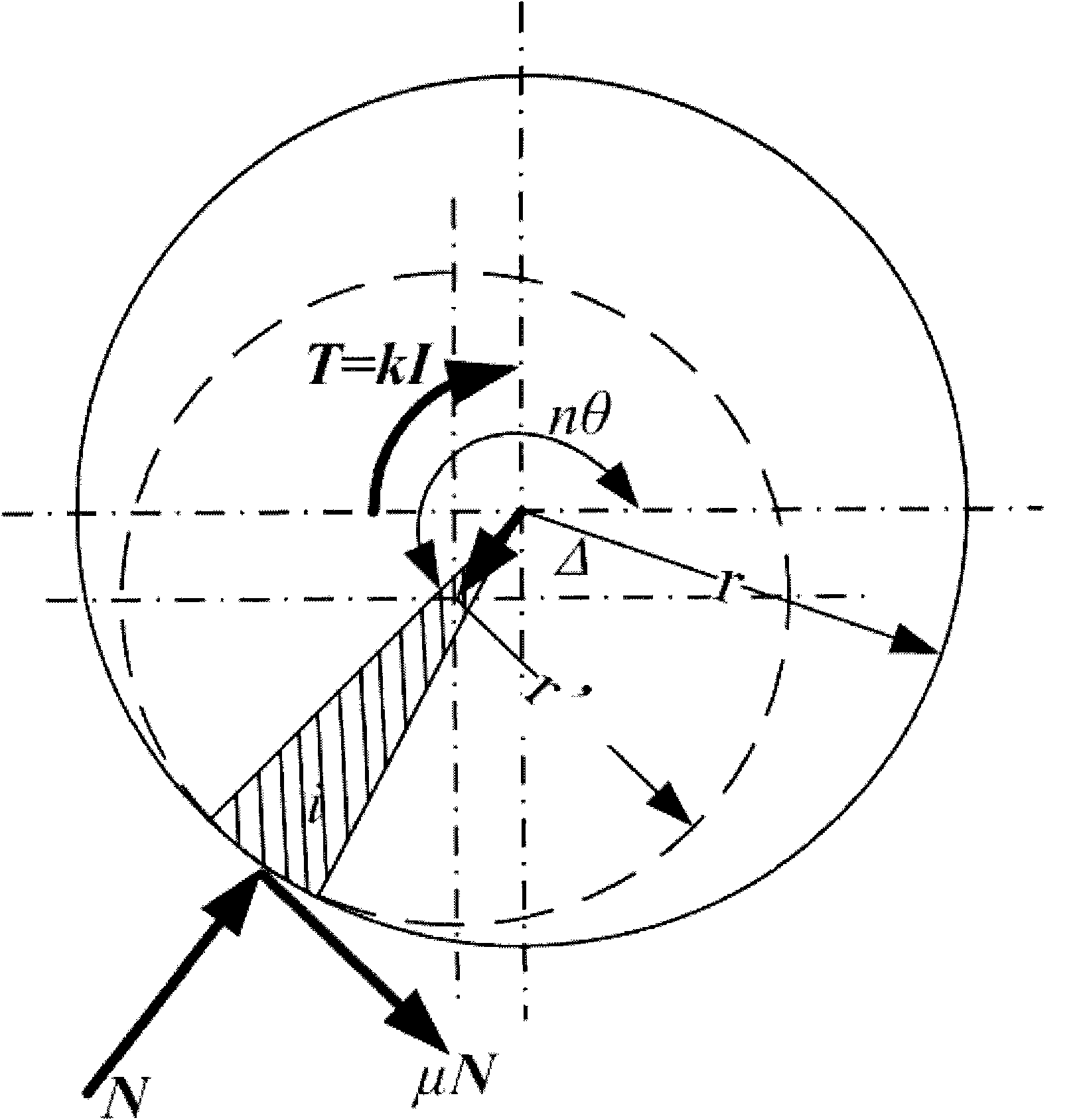
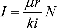
[0009] According to an embodiment of the present invention, a method for detecting the diameter of a polishing wheel is provided, which is characterized by comprising: detecting a current I flowing through a spindle motor driving the polishing wheel; and determining a diameter d of the polishing wheel according to the current.

[0010] According to a further embodiment of the present invention, the above-mentioned current I is the current flowing through the primary circuit of the spindle motor driving the polishing wheel.

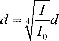
[0011] According to a further embodiment of the present invention, the above method is further characterized in that: a current sensor is used to detect the current I; the diameter d of the polishing wheel is determined according to the following formula:

[0012] d = I ...


PUM


Abstract

The invention provides a polishing wheel diameter and polishing force detection method, relating to real-time polishing force detection, polishing wheel diameter detection and polishing wheel wear compensation. The size of a polishing force in a polishing process is indirectly measure and a polishing wheel diameter is measured when a main motor is started by adopting a current sensor according to the proportionate relationship between measured factors and read values of the current sensor; and in a real-time polishing process, because a polishing wheel is worn to cause the reduction of the polishing force, the normal direction of a contact surface of the polishing wheel and a workpiece is calculated according to the position of a polishing contact fan sector appointed by a current user in the polishing wheel and the corner of a rotating shaft at the tail end of the current polishing wheel so that the compensation distance of each movable joint can be rapidly figured out in real time.

Description

technical field [0001] The invention relates to a method for detecting the diameter of a polishing wheel, a method for detecting a polishing force, and a method for compensating the wear of a polishing wheel. Smaller, a diameter detection and compensation method. Background technique [0002] With the improvement of people's requirements for product shape and surface quality, polishing is often used in the product finishing process. Especially for the polishing of complex curved surfaces such as high-end plumbing equipment, stationery, aero-engine blades, turbine blades, etc., generally only manual work can be used, which is not only time-consuming, labor-intensive, inefficient, but also has poor product consistency and low precision. CNC polishing systems such as robotic polishing systems use programming control to realize automatic polishing operations. It not only improves the working conditions of workers and improves production efficiency, but also greatly improves the...

Claims


Application Information

Patent Timeline
Patent Type & Authority Applications(China)
IPC IPC(8): B24B49/10
Inventor 王伟张栋贠超张令
Owner BEIHANG UNIV
Why Eureka
Try Eureka