Winding shaft

A technology of winding shaft and spindle, applied in the direction of winding strip, thin material processing, transportation and packaging, etc., can solve the problems of inability to expand, small contact area, and inability to sterilize the surface of the paper tube.

Active Publication Date: 2013-04-10
江阴市秀祥卷轴有限公司
View PDF0 Cites 0 Cited by
  • Summary
  • Abstract
  • Description
  • Claims
  • Application Information

AI Technical Summary

Problems solved by technology

[0002] At present, the domestic and imported winding shafts used in the market adopt the airbag type or friction type winding method, because the contact area between the expansion part of the winding shaft and the inner diameter of the winding core tube is small, so it cannot be expanded and thinner And narrower materials (such as steel pipes and soft plastic tubes), can only barely expand the paper tube. During the winding process of the paper tube, the expansion force of the paper tube will exceed the expansion force of the rewinding paper tube. It will slip on the expansion part of the winding shaft, and paper scraps will fall out, polluting the wound material and the working environment, and the surface of the paper tube cannot be sterilized, so the paper tube cannot be used for coils with high hygienic requirements. winding materials, and the recycling rate of paper tubes is low, which does not meet the current low-carbon environmental protection requirements

Method used


Image

  • Winding shaft
  • Winding shaft
  • Winding shaft

Examples


Embodiment Construction

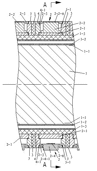
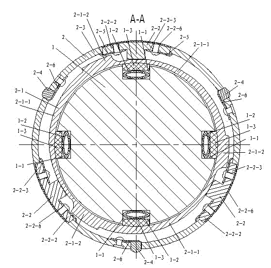
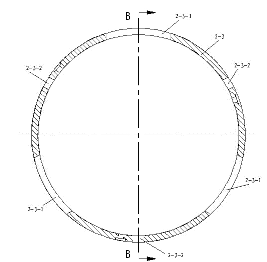
[0017] The present invention is described in further detail below in conjunction with the embodiment that accompanying drawing provides.

[0018] As shown in 1 to 8, a winding shaft is composed of a plurality of expansion rings 2 mounted on the main shaft 1 in series, and the expansion rings 2 include a guide seat 2-1 and a plurality of arc-shaped sliders 2-2 and a plurality of friction parts 2-4, the guide seat 2-1 is set on the main shaft 1, the left side of the guide seat 2-1 is fixedly connected with the first annular cover plate 4, and the right side is fixedly connected with the second annular cover plate 5, There are friction rings 3 between adjacent expansion rings 2, and the friction rings 3 are set on the main shaft 1. There are a plurality of axial grooves 1-1 on the outer periphery of the main shaft 1, and there are gas-filled tubes 1 in the axial grooves 1-1. -2 and friction strip 1-3, the inflation tube 1-2 is located at the bottom of the axial groove 1-1, the bo...


PUM


Abstract

The invention discloses a winding shaft which is formed in a way that a plurality of expansion rings are serially connected to a main shaft, wherein each expansion ring comprises an outer ring, a first reset spring piece and a second reset spring piece, the periphery of a guide seat is provided with a plurality of arc incline sliding sections, the outer ring is sleeved on the periphery of the guide seat, the outer ring is provided with a plurality of slide block holes and a plurality of friction piece holes, the tops of arc slide blocks are inserted into the corresponding slide holes, the tops of the arc slide blocks can partially exceed the outer surface of the outer ring when sliding, the bottom surfaces of the arc slide blocks support against the arc incline sliding sections of the guide seat, one end of the first reset spring piece is fixedly connected with the arc slide blocks and the other end supports against the inner hole wall of the outer ring, friction pieces are inserted into the corresponding friction piece holes of the outer ring, one end of the second reset spring piece is fixedly connected with the outer ring and the other end supports against the bottoms of the friction pieces, and the tops of the friction pieces exceed the outer surface of the outer ring. A steel pipe and a plastic pipe can be tensioned, and the winding material with high sanitation requirement can be wound, thus the winding shaft has a wide application range.

Description

technical field [0001] The invention relates to a series-mounted friction winding shaft used in conjunction with mechanical equipment, especially suitable for disposing in machinery for cutting, winding, unwinding and rewinding of plastics, packaging, paper plastics and ultra-thin metal films, etc. on the device. Background technique [0002] At present, the domestic and imported winding shafts used in the market adopt the airbag type or friction type winding method. Because the contact area between the expansion part of the winding shaft and the inner diameter of the winding core tube is small, it cannot be expanded and thinner. And narrower materials (such as steel pipes and soft plastic tubes), can only barely expand the paper tube. During the winding process of the paper tube, the expansion force of the paper tube will exceed the expansion force of the rewinding paper tube. It will slip on the expansion part of the winding shaft, and paper scraps will fall out, pollutin...

Claims


Application Information

Patent Timeline
Patent Type & Authority Patents(China)
IPC IPC(8): B65H18/26
Inventor 谢梅宋伯祥
Owner 江阴市秀祥卷轴有限公司
Why Eureka
Try Eureka