Air supply control method for equipment in machine room

A control method and equipment technology, applied in heating and ventilation control systems, lighting and heating equipment, heating methods, etc., can solve the problems of large energy consumption and inaccurate temperature control in listed computer rooms

Inactive Publication Date: 2011-07-06
潘华建
View PDF6 Cites 52 Cited by
  • Summary
  • Abstract
  • Description
  • Claims
  • Application Information

AI Technical Summary

Problems solved by technology

[0006] In view of this, the present invention is to provide a method for controlling air supply of computer room equipment to solve the problems of large energy consumption and inaccurate temperature control in listed computer rooms

Method used


Image

  • Air supply control method for equipment in machine room
  • Air supply control method for equipment in machine room
  • Air supply control method for equipment in machine room

Examples


Embodiment Construction

[0038] In order to clearly illustrate the solutions in the present invention, preferred embodiments are given below in detail.

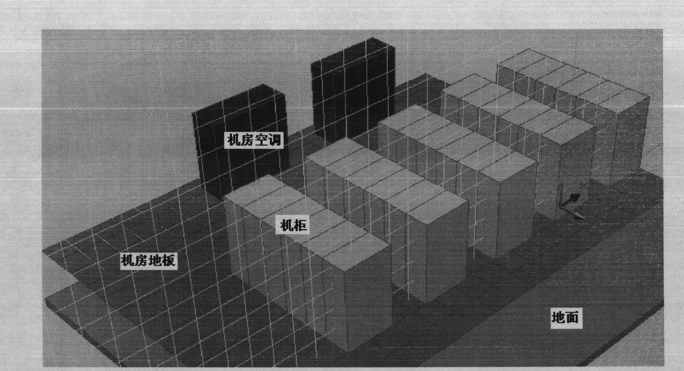
[0039] The air supply adjustment system in the embodiment of the present invention includes: a cold pool system, an air supply control system, and a central control system.

[0040] In the present invention, an air supply controller is installed on the cabinet to adjust the temperature in the cabinet; and the air supply controller is connected to a central control system to adjust the total air volume and total cooling capacity of the air conditioner in the entire machine room through the central control system. Describe in detail below by accompanying drawing.

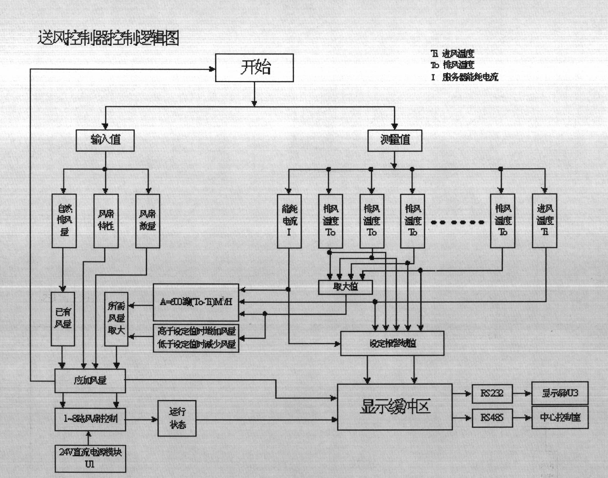
[0041] The air supply controller of the method of the present invention is designed according to the 2U chassis, and can be directly installed on the vacancy in the controlled cabinet (or the adjacent cabinet). The air supply controller can be in accordance with figure 2 The logic block d...


PUM


Abstract

The invention discloses an air supply control method for equipment in a machine room, comprising the following steps: an air supply controller receives induction values of temperature sensors at an air inlet and an air outlet in a machine cabinet and receives induction value of running current in the machine cabinet; the induction values are calculated by a presetting computing formula, a corresponding air quantity regulation value can be obtained according to the calculated value; the quantity and rotating speed of the fans at the position of the air inlet can be controlled according to the regulation value, so as to regulate the air inlet quantity; and a cabinet door of the machine cabinet is connected with a cold pool cabinet body forming an air flow circulating space, the cold pool cabinet body comprises an air inlet passage arranged at the top or bottom of the cold pool cabinet body and a fan module for regulating air quantity. A central control system calculates the received temperature values in all machine cabinets, the running current values of the machine cabinets, the needed air quantity values of the machine cabinets, the self-measuring temperature values of the machine cabinets and the running power values of the machine cabinets by a setting computing formula, so as to control a switching on/off state of the air conditioner connected with the air inlet passage and regulate the total air quantity and the total refrigerating capacity.

Description

technical field [0001] The invention relates to automatic temperature control, in particular to an air supply control method for equipment in a machine room. Background technique [0002] With the development of Internet technology and communication industry, the density of each data center and communication center is increasing with the expansion of business. However, due to many defects in the construction of the previous computer room, it cannot meet the development requirements of modern communication center and data center computer room. , There have been many problems, such as local overheating, high energy consumption, and low computer room density. These problems are common problems in the original (before 2009) design of the computer room, which directly restricted the development of the computer room, especially the high energy consumption. [0003] According to statistics, my country is now the second largest energy consumer after the United States, but at the sam...

Claims


Application Information

Patent Timeline
Patent Type & Authority Applications(China)
IPC IPC(8): F24F11/00
Inventor 潘华建田松林穆易楠
Owner 潘华建
Why Eureka
Try Eureka