Burning pipeline system for rotary hearth furnace

A rotary hearth furnace and combustion tube technology, used in furnaces, iron hot blast stoves, furnace types, etc., can solve the problems that combustion-supporting medium and fuel medium cannot be independently controlled, and the production process of reduced iron cannot be accurately controlled, etc. precise effect

Active Publication Date: 2012-09-26
ZHONGYE-CHANGTIAN INT ENG CO LTD
View PDF0 Cites 0 Cited by
  • Summary
  • Abstract
  • Description
  • Claims
  • Application Information

AI Technical Summary

Problems solved by technology

[0004] However, in the prior art, the combustion-supporting medium and fuel medium delivery pipelines are integrally distributed outside the cover of the rotary hearth furnace, and the amount of combustion delivered to each valve is generally controlled, that is, the combustion-supporting medium and fuel delivered to each valve are The amount of medium is the same, and it cannot independently control the amount of combustion-supporting medium and fuel medium delivered to each section of the furnace according to the requirements of different processes, so that the production process of reduced iron in each section of the furnace cannot be accurately controlled

Method used


Image

  • Burning pipeline system for rotary hearth furnace
  • Burning pipeline system for rotary hearth furnace
  • Burning pipeline system for rotary hearth furnace

Examples


Embodiment Construction

[0021] The following will clearly and completely describe the technical solutions in the embodiments of the present invention with reference to the accompanying drawings in the embodiments of the present invention. Obviously, the described embodiments are only some, not all, embodiments of the present invention. Based on the embodiments of the present invention, all other embodiments obtained by persons of ordinary skill in the art without making creative efforts belong to the protection scope of the present invention.

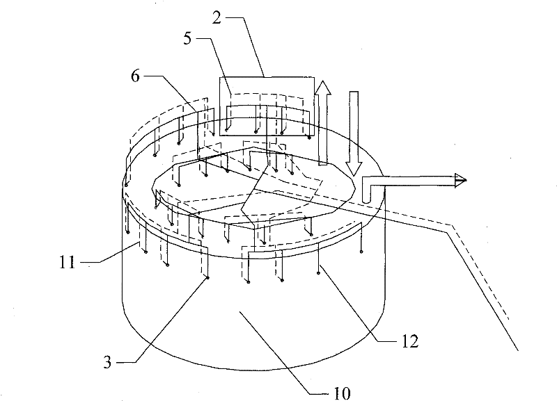
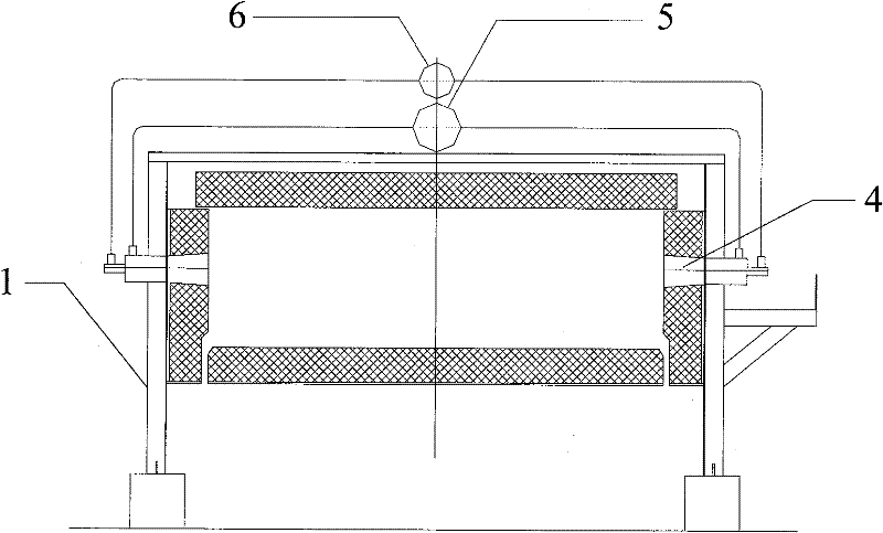
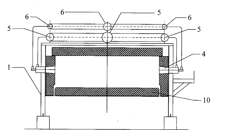
[0022] Please refer to the attached figure 1 And attached figure 2 , Embodiment 1 of the present invention discloses a combustion piping system for a rotary hearth furnace, comprising: a valve group 2 , a valve 3 , a combustion-supporting medium delivery pipeline 5 and a fuel medium delivery pipeline 6 .

[0023] The valve group 2 is arranged on the cover body 1 of the rotary hearth furnace in sections, and a plurality of valves 3 are also provided in each s...


PUM


Abstract

The invention discloses a burning pipeline system for a rotary hearth furnace. The burning pipeline system for the rotary hearth furnace comprises a combustion-supporting medium conveying pipeline, a fuel medium conveying pipeline and a valve group consisting of a plurality of valves, wherein the valve group is arranged on a cover body of the rotary hearth furnace section by section; the combustion-supporting medium conveying pipeline and the fuel medium conveying pipeline are independently and respectively connected with the valves in the valve group section by section; and the number of sections of the combustion-supporting medium conveying pipeline and the fuel medium conveying pipeline is the same as the number of sections of the valve group. By adopting the burning pipeline system ofthe rotary hearth furnace and using the sectioned valve group arranged on the cover body of the rotary hearth furnace, the valves independently exist in groups and sections; meanwhile, independent control over the quantity of the gas conveyed to each valve according to different process requirements can be realized by using the combustion-supporting medium conveying pipeline and the fuel medium conveying pipeline which are independently connected with the valves in each section of valve group, so the demanded quantity of the gas of each section in the rotary hearth furnace can be controlled precisely.

Description

technical field [0001] The invention relates to the technical field of metallurgical equipment, in particular to a rotary hearth furnace combustion piping system. Background technique [0002] At present, in the iron and steel smelting industry, a rotary hearth furnace is generally used to reduce the materials composed of reducing materials and iron oxides to produce reduced iron; the reducing materials and iron oxides are mixed and pressed into balls, and evenly arranged in the rotary At the bottom of the hearth furnace, in the process of reducing iron in the rotary hearth furnace, the high temperature obtained by burning the fuel medium is used to reduce the iron oxide mixed with the reducing material. The nozzle input on the side wall of the furnace has an ignition device at the nozzle, which can ignite the mixture of the input combustion-supporting medium and fuel medium. The conveying pipelines for conveying combustion-supporting medium and fuel medium are usually arra...

Claims


Application Information

Patent Timeline
Patent Type & Authority Patents(China)
IPC IPC(8): C21B9/08F27B9/36
Inventor 沈维民贺新华肖祖泉
Owner ZHONGYE-CHANGTIAN INT ENG CO LTD
Why Eureka
Try Eureka