Active RFID (radio frequency identification device) tamper-proof label based on optical fibre transmission energy density detection

A technology of energy density and optical fiber transmission, which is applied to record carriers used in machines, photometry using electrical radiation detectors, instruments, etc. It can solve problems such as low safety, high failure rate, and inability to effectively guarantee illegal removal detection.

Inactive Publication Date: 2011-07-06
上海锐帆信息科技有限公司
View PDF2 Cites 2 Cited by
  • Summary
  • Abstract
  • Description
  • Claims
  • Application Information

AI Technical Summary

Problems solved by technology

[0003] In order to overcome the existing problems in the existing active tamper-resistant tags, such as the inability to effectively guarantee illegal removal detection, low safety, and high failure rate, the present invention proposes an implementation mechanism for active RFID tamper-resistant tags based on optical fiber transmission energy density detection, Its specific content includes abandoning the traditional design method, and not using any mechanical and physical means to form an electronic circuit for anti-dismantlement in the active electronic tag, but using an optical circuit based on optical fiber, using optical fiber to achieve almost zero Loss of transmission characteristics, through the detection of changes in the energy density transmitted on the optical circuit to achieve tamper-proof design, this mechanism effectively prevents malicious attacks on the optical fiber circuit using optical bypass, with a very high level of security protection, very good Excellent external complex environment adaptability and high working reliability completely solve the problems caused by electrical circuit detection in mechanical and physical methods

Method used


Image

  • Active RFID (radio frequency identification device) tamper-proof label based on optical fibre transmission energy density detection
  • Active RFID (radio frequency identification device) tamper-proof label based on optical fibre transmission energy density detection
  • Active RFID (radio frequency identification device) tamper-proof label based on optical fibre transmission energy density detection

Examples


Embodiment Construction

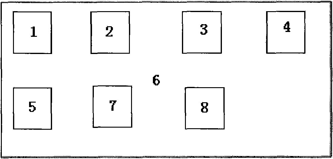
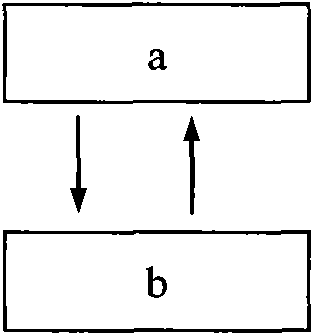
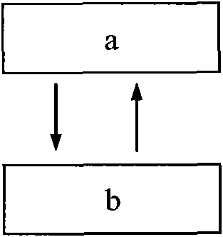
[0016] Normally 6 is in state a;

[0017] After the counter counts to a certain cycle time T1, trigger 2 to enter state b;

[0018] The time length of state b is T2, and the task of detecting the energy density state of optical fiber transmission and sending the identification information of the label is completed within the T2 period. After T2 ends, 6 returns to state a;

[0019] When the tag is removed from the identification object, the energy density state of the optical fiber transmission changes, causing the state feature code in the ID identification information to change. In the next T2 state, the identification information containing the state feature code change is sent, and T2 ends Then 6 returns a;

[0020] Re-enter the next round of working state cycle.


PUM


Abstract

The invention discloses an active RFID (radio frequency identification device) tamper-proof label based on optical fibre transmission energy density detection. For overcoming the problems that the existing active tamper label cannot effectively ensure to detect illegal tamper, and is low in safety and high in failure rate, and the like, the active radio frequency identification technology and the optical fibre transmission energy density detection technology are combined to form the active RFID tamper-proof design based on the optical fibre transmission energy density detection. An active tamper-proof label ID number is formed by combining fixed ID identifying information built in a radio frequency identification unit and an optical fibre transmission energy density state condition code which is obtained by using an internal micro processing unit of the radio frequency identification to control and detect the change of energy density in an optical transmission channel dynamically. The active RFID tamper-proof label only sends out the number information consisting of the fixed ID identity and the state condition code of the label in a periodic small time window in a wireless mode, and is at the dormant state normally.

Description

Technical field [0001] The invention relates to a realization method suitable for low power consumption active anti-tampering electronic tags. Background technique [0002] Patents of the People's Republic of China 200810034876.2 "A Realization Method for Active Read-Only Tamper-proof Electronic Tags" and 200820059466.9 "Anti-Disassembly Electronic Tags" disclose two anti-tamper design methods for active tags, but they have the following disadvantages: 1 ) Active tag tamper-proof design uses mechanical and physical methods such as pressure or magnetism and metal wires to form an electronic circuit to protect the active tag from being removed from being attached to the object. These mechanical and physical methods are easy to be bypassed, shorted, etc. 2) The mechanical and physical methods such as pressure, magnetism, and metal wires are used to detect the on-off status of the electronic circuit formed in this way, and no more secure method is used. The way of transmitting ...

Claims


Application Information

Patent Timeline
IPC IPC(8): G06K19/073G01J1/42
Inventor 徐双欧海涛赵明
Owner 上海锐帆信息科技有限公司
Why Eureka
Try Eureka