Static transfer switch device, power supply apparatus using the switch device and switching method thereof

a technology of switching device and switch device, which is applied in the direction of electronic switching, emergency power supply arrangement, pulse technique, etc., can solve the problems of reducing the quality of electrical power, affecting the reliability of information communication systems, and causing a large amount of economic damage, so as to reduce the failure rate of semiconductor switches, reduce the operation time, and supply power to a load stably and safely

Inactive Publication Date: 2010-10-21
KT CORP
View PDF11 Cites 46 Cited by
  • Summary
  • Abstract
  • Description
  • Claims
  • Application Information

AI Technical Summary

Benefits of technology

[0015]Also, since the mechanical or electrical contact point switches are turned on/off together with the semiconductor switches, load current during operation is supplied through the mechanical or electrical contact point switches. Thus, the problem associated with harmonics generated in an SCR switch of a static transfer switch can be eliminated fundamentally.
[0016]In addition, the present invention prevents power supply from being superposed when power supply path is switched by a switch. Therefore, even if the static transfer switch is broken down, it can prevent the failure of the static transfer switch from affecting a load and an input UPS.
[0023

Problems solved by technology

These information communication systems cannot secure reliability without very stable power supply.
Undesired voltage variation may degrade the quality of electrical power, electronic equipment may malfunction, stop operation, or even cause fire.
Also,

Method used


Image

  • Static transfer switch device, power supply apparatus using the switch device and switching method thereof
  • Static transfer switch device, power supply apparatus using the switch device and switching method thereof
  • Static transfer switch device, power supply apparatus using the switch device and switching method thereof

Examples


first embodiment

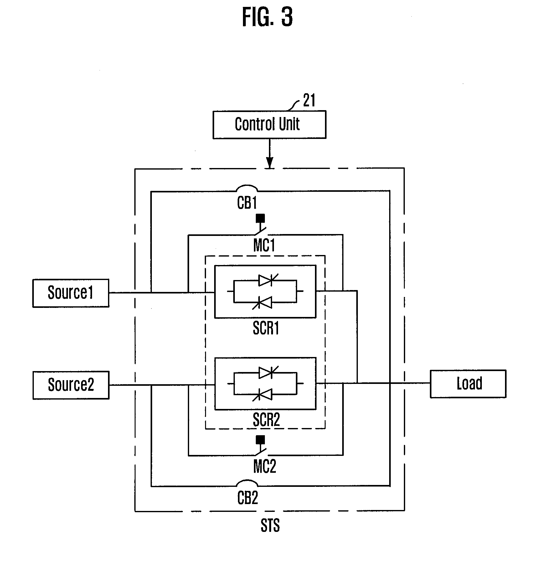
[0036]FIGS. 3 and 4 are schematic diagrams illustrating a static transfer switch for static power supply and a power supplying apparatus using the static transfer switch in accordance with the present invention.

[0037]In FIGS. 3 and 4, the same reference numerals are given to the same constituent element shown in FIG. 1.

[0038]Referring to FIG. 3, the power supplying apparatus according to the first embodiment of the present invention includes first and second UPSs (Source1 and Source2), which are power sources, and a static transfer switch. The static transfer switch includes first and second SCR switches (SCR1 and SCR2), first and second magnetic (MC) switches or first and second motor driving (MCC) switches, and first and second manual circuit brakes (CB1 and CB2). Hereafter, the first and second magnetic (MC) switches or first and second motor driving (MCC) switches will be referred to as motor driving switches (MC1 and MC2).

[0039]In the first embodiment of the present invention, ...

second embodiment

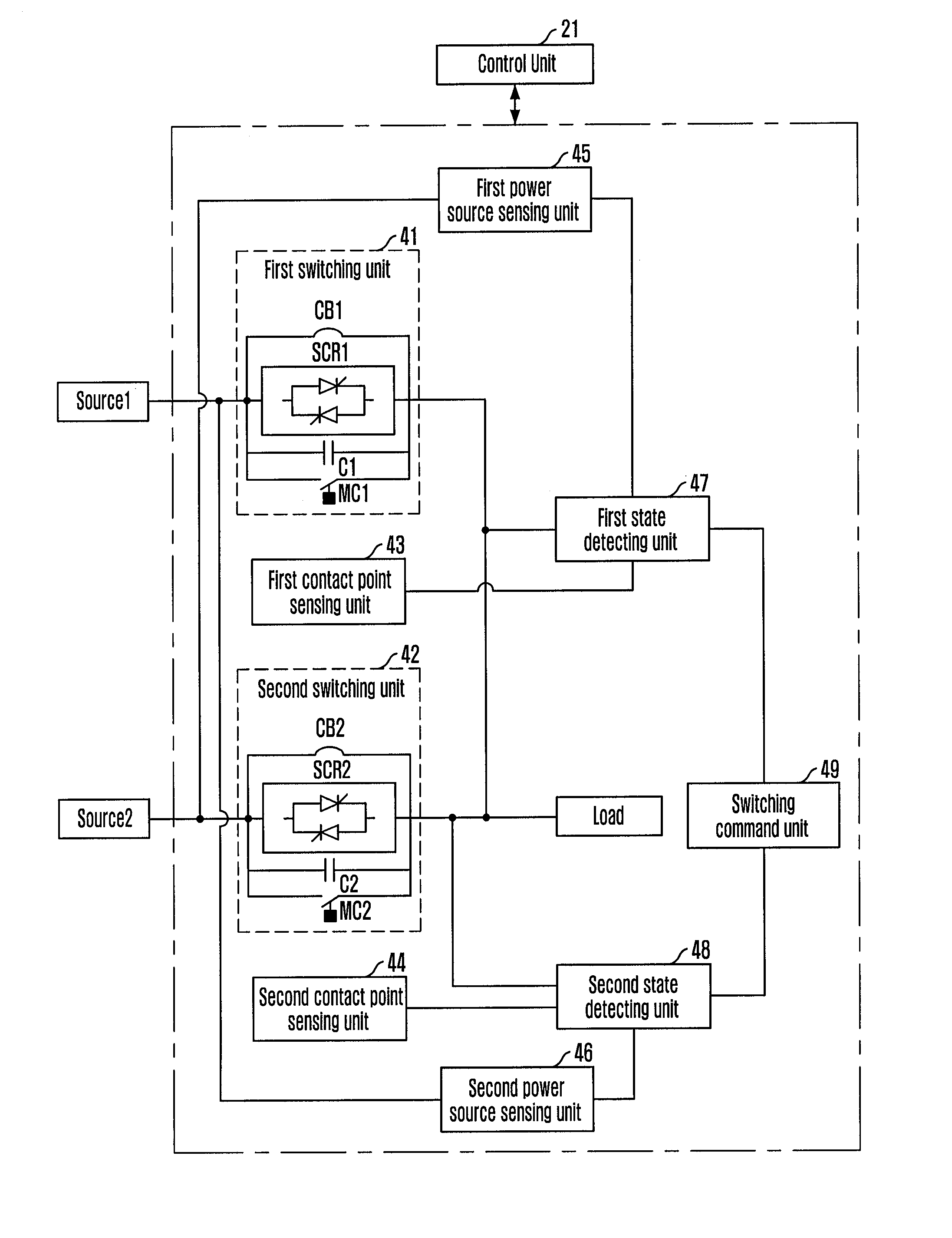
[0065]FIG. 6 is a block diagram describing a static transfer switch for static power supply which resolves a problem that may occur in the structure of FIG. 1 and a structure of a power supplying apparatus in accordance with the present invention.

[0066]Hereafter, the same reference numerals are given to the constituent elements of the same function shown in FIGS. 3 and 4, and description on them will not be provided herein.

[0067]Referring to FIG. 6, the power supplying apparatus according to the second embodiment of the present invention includes first and second UPSs (Source1 and Source2), which are power sources, and a static transfer switch. The static transfer switch includes first and second switching units 41 and 42, first and second contact point sensing units 43 and 44, first and second power source sensing units 45 and 46, first and second state detecting units 47 and 48, and a switching command unit 49.

[0068]The first switching unit 41 includes the first SCR switch (SCR1) ...


PUM


Abstract

Disclosed is a static transfer switch with a modified structure that can selectively supply power from power sources to a load stably and continuously, a power supplying apparatus employing the same, and a switching method thereof. The present invention includes mechanical/electrical contact point switches in parallel to semiconductor switches, and minimizes operation time of the semiconductor switches by turning on/off the mechanical or electrical contact point switches together when the semiconductor switches are turned on/off to reduce a failure rate of the semiconductor switch. Also, the static transfer switch makes a switching unit electrically/mechanically separable from a power source with failure to switch a power supply path and thereby prevent superposition caused by the switching unit. This prevents a problem caused when electrical or mechanical contact point switches simply in parallel, that is, a problem that power sources are turned on simultaneously when the power supply paths are switched.

Description

TECHNICAL FIELD[0001]The present invention relates to a static transfer switch (STS) for supplying static power source, a power supplying apparatus using the static transfer switch, and a switching method thereof. More particularly, the present invention relates to a static transfer switch that is provided at output ends of a plurality of power sources operating in parallel and when any one power source malfunctions, a power supplying path is switched from the malfunctioning power source to another power source to selectively supply power to a load so that power is supplied stably and continuously, a power supplying apparatus, and a switching method thereof.BACKGROUND ART[0002]Rapid progress in electrical, electronic, information communication technologies combines information communication systems, such as computers, switches, transmission equipment, repeaters, and servers, closely and organically. These information communication systems cannot secure reliability without very stabl...

Claims


Application Information

Patent Timeline
IPC IPC(8): H02J4/00H03K17/56
CPCH01H9/541H02J9/061H01H2300/018H02J9/06
Inventor JUNG, HYUN-CHULKIM, JUNG-BONG
Owner KT CORP
Why Eureka
Try Eureka