Low-scattering plane-reflective array antenna

A plane reflection and array antenna technology, applied in the field of plane reflection array antenna and platform design of stealth weapons, can solve the problems of limited application range and strong antenna scattering characteristics, and achieve the effect of avoiding gain reduction, low RCS, and reducing impact.

Inactive Publication Date: 2013-09-25
GUANGDONG MIKWAVE COMM TECH
View PDF3 Cites 0 Cited by
  • Summary
  • Abstract
  • Description
  • Claims
  • Application Information

AI Technical Summary

Problems solved by technology

This kind of reflectarray antenna is small in size and light in weight, but the biggest disadvantage of this kind of antenna is its strong scattering characteristics. When it is applied to weapons and equipment in modern warfare, it is easy to be detected and found by enemy radar, and its application range is limited.

Method used


Image

  • Low-scattering plane-reflective array antenna
  • Low-scattering plane-reflective array antenna
  • Low-scattering plane-reflective array antenna

Examples


Embodiment Construction

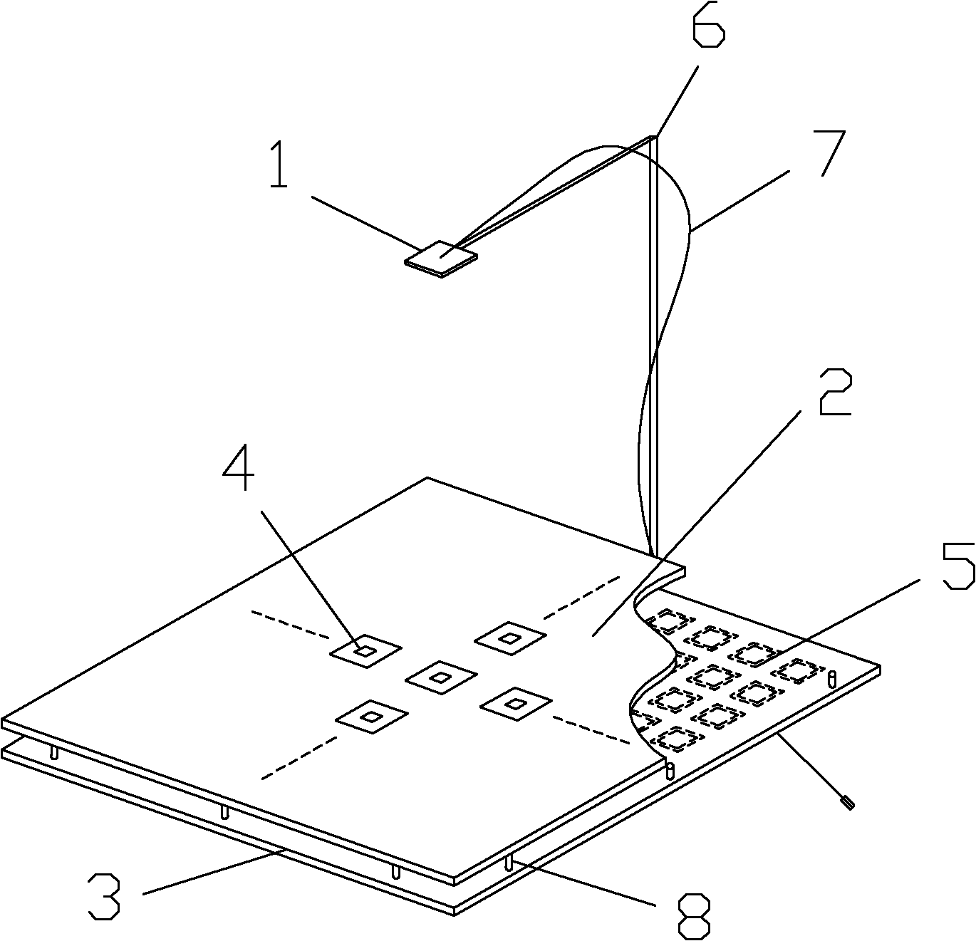
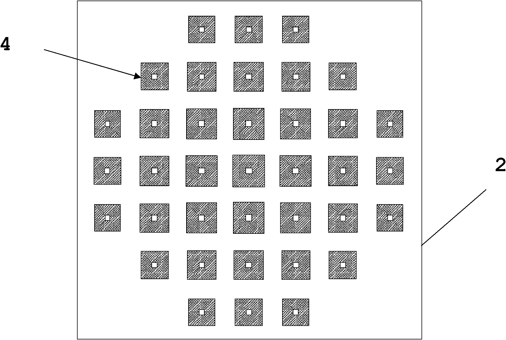
[0030] see figure 1 , The low-scattering planar reflectarray antenna of the present invention consists of a feed source 1, an upper dielectric board 2, a lower dielectric board 3, a radiation array 4, a frequency selective surface 5, a support frame 6, a feeder 7 and a support screw 8. The feed source 1 is fixed at a distance of 400mm from the front of the upper dielectric board 2 through the support frame 6; the radiation array 4 is printed on the front of the upper dielectric board 2, and the frequency selection surface 5 is printed on the back of the lower dielectric board 3; the upper dielectric board 2 There is an air medium between the back of the bottom and the front of the lower dielectric board 3, and the two dielectric boards are fixed by support screws 8; the antenna feeds the feed source 1 through the feeder line 7, and the feeder line is placed along the support frame.

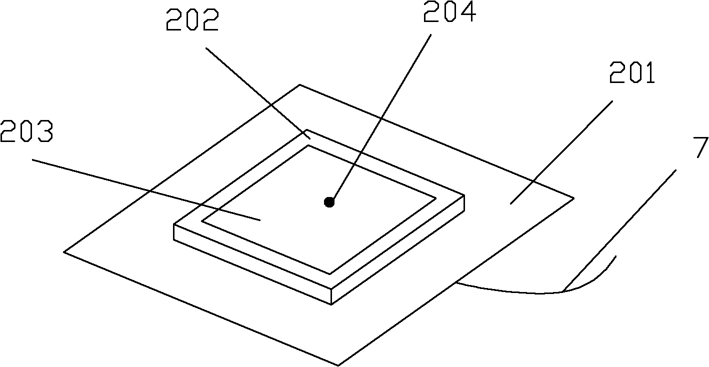
[0031] see figure 2 , the feed source 1 of the present invention adopts the form of a rectan...


PUM


Abstract

The invention discloses a low-scattering plane-reflective array antenna mainly solving the problem between the radiation characteristic and the low RCS (Radar Cross Section) characteristic of the traditional antenna. The antenna comprises a feed source (1), an upper medium plate (2), a lower medium plate (3), a radiation array (4), a frequency selection surface (5) and a support frame (6), wherein the feed source (1) adopts a rectangular microstrip structure and is fixed above the upper medium plate (2) through the support frame (6); the radiation array (4) is formed by arranging a plurality of hollow square or hollow round radiation units (40) in a round area and printed on the front of the upper medium plate (2); the frequency selection surface (5) is formed by arranging a plurality of same hollow square or hollow round frequency selection units (501) in a rectangular area and printed on the back of the lower medium plate (3); and the upper medium plate is in clearance fixation with the lower medium plate. Through the low-scattering plane-reflective array antenna, the RCS of the reflective array antenna can be effectively reduced; and the low-scattering plane-reflective array antenna can be directly applied to the invisible design of weapon platforms.

Description

technical field [0001] The invention belongs to the technical field of antennas, in particular to a planar reflection array antenna, which can be used in the platform design of stealth weapons. Background technique [0002] With the rapid development of information technology, modern detection equipment and weapon systems are developing toward intelligence, high precision, and long-distance. The traditional combat weapons' ability to survive, penetrate and strike on the battlefield is seriously threatened. The emergence of stealth technology has greatly improved the survivability and combat capability of weapons and equipment, especially the deep strike capability. Stealth technology has become one of the most important and effective penetration tactics and technical means in the three-dimensional modern warfare integrating land, sea, air, sky, and electromagnetic six dimensions, and has been highly valued by countries all over the world. In modern warfare, radar is still o...

Claims


Application Information

Patent Timeline
Patent Type & Authority Patents(China)
IPC IPC(8): H01Q21/06H01Q15/22H01Q1/38H01Q19/10
Inventor 徐云学赵晋娟龚书喜刘英张鹏飞任立石
Owner GUANGDONG MIKWAVE COMM TECH
Why Eureka
Try Eureka