
Condensation dryer with a heat pump and recognition of an impermissible operating state and method for the operation thereof

An operating state, dryer technology, used in household dryers, household appliances, textiles and papermaking, etc., can solve problems such as inaccurate identification

Active Publication Date: 2011-07-06
BOSCH SIEMENS HAUSGERATE GMBH
View PDF4 Cites 8 Cited by
  • Summary
  • Abstract
  • Description
  • Claims
  • Application Information

AI Technical Summary

Problems solved by technology

In any case, in this way impermissible operating states in condensing dryers equipped with a heat pump can only be detected inaccurately

Method used


Image

  • Condensation dryer with a heat pump and recognition of an impermissible operating state and method for the operation thereof
  • Condensation dryer with a heat pump and recognition of an impermissible operating state and method for the operation thereof
  • Condensation dryer with a heat pump and recognition of an impermissible operating state and method for the operation thereof

Examples


Embodiment Construction

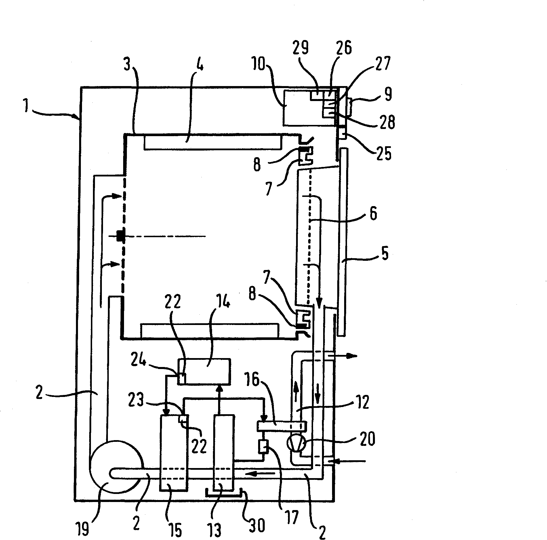
[0051] figure 1 A condensation dryer according to a first embodiment variant (hereinafter simply referred to as "dryer") is shown in vertical section, wherein the process air is only heated via the condenser of the heat pump.

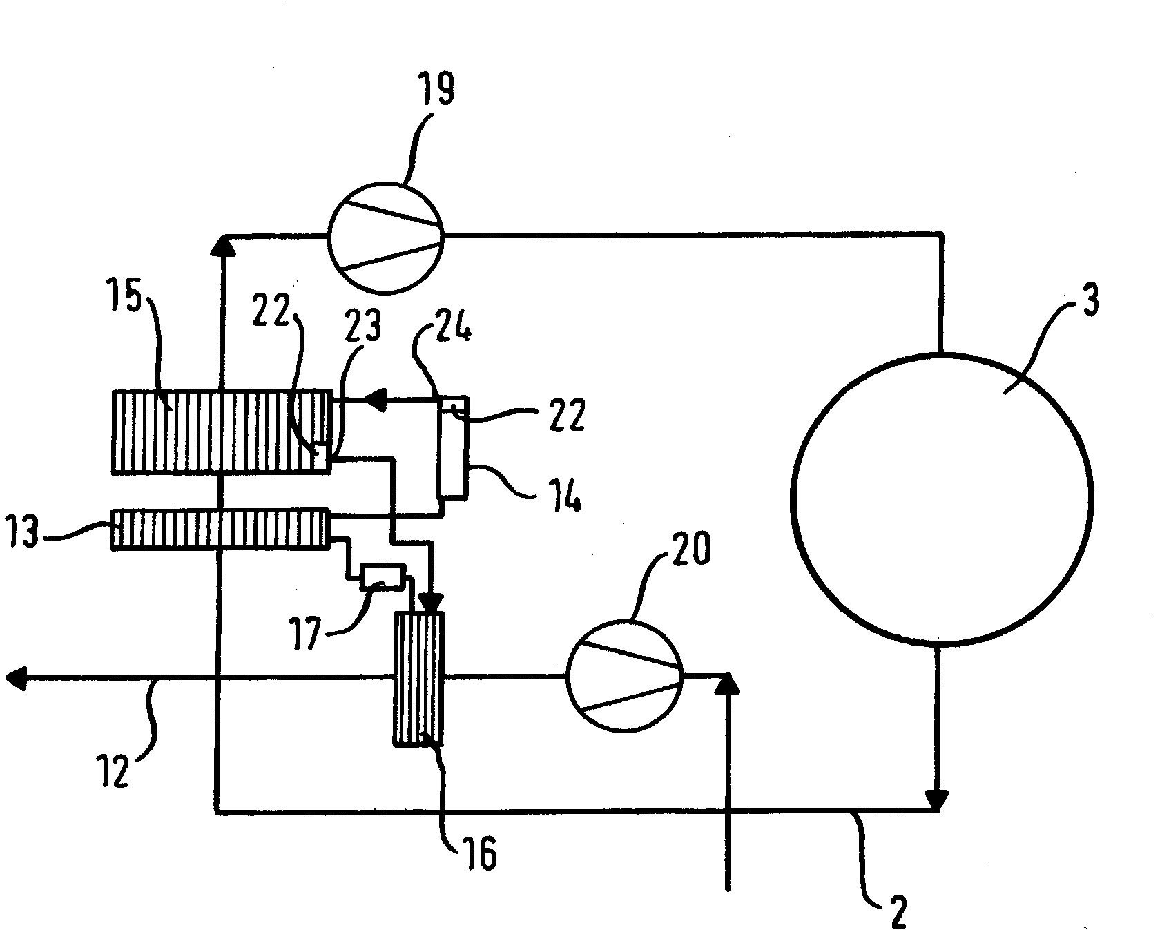
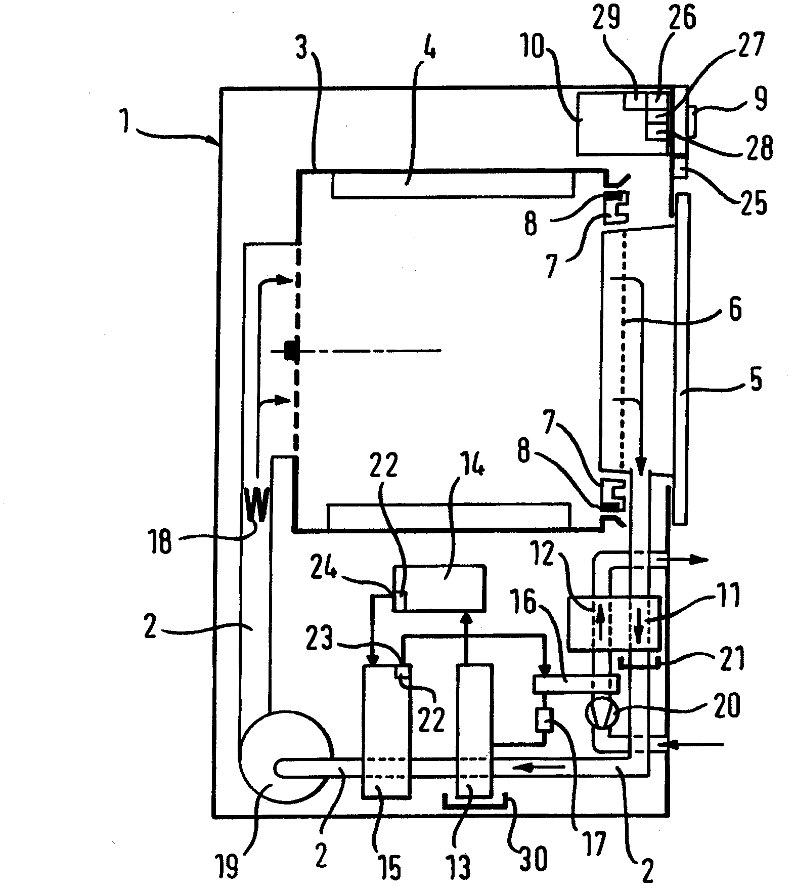
[0052] figure 1The dryer 1 shown in has a drum rotatable about a horizontal axis as a drying chamber 3 in which a lifting structure 4 for moving laundry while the drum is rotating is fixed. The process air is conveyed by means of a first fan 19 through the drum 3 and the heat pumps 13 , 14 , 15 , 17 in a closed circuit in the air channel 2 (process air circuit 2 ). The process air heated in the condenser 15 of the heat pumps 13 , 14 , 15 , 17 is cooled and absorbs moisture after passing through the drum 3 and is heated again by means of the condenser 15 after the moisture contained in the process air has been condensed. The heated air is conducted here from the rear side, ie through the perforated bottom of the drum, from the side of the drum 3 oppo...


PUM


Abstract

The invention relates to a condensation dryer 1 with a drying chamber 3 for the objects to be dried, a process air circuit 2, a first fan 19 in the process air circuit 2, a heat pump 13, 14, 15, 17 in which a coolant circulates, an evaporator 13, a compressor 14, a condenser 15 and a throttle 17 as well as a temperature sensor 22 for measuring a temperature of the coolant, and a controller 10. The controller 10 comprises a first means 26 for comparing a temperature TK of the coolant to an upper temperature limit TK lim1 stored in the controller 10; second means 27 for shutting off the compressor 14 when TK is greater than or equal to TK lim1, and for turning on the compressor 14 after a respective shut off; a counting device 28 for determining a number n of cases in which the compressor 14 has been shut off, said counting device 28 being incremented by 1 every time a shutoff occurs; and third means 29 for comparing the number n with a pre-determined limiting number nlim stored in the controller 10 and for evaluating the difference Delta n = (n - nlim) in relation to the existence of an impermissible operating state. The invention further relates to a method for operating the condensation dryer.

Description

technical field [0001] The invention relates to a condensation dryer having: a drying chamber for items to be dried; a process air circuit; a first fan in the process air circuit; a heat pump in which a refrigerant circulates , and the heat pump has an evaporator, a compressor, a condenser, and a throttle valve; a temperature sensor for measuring the temperature of refrigerant; and a controller. The invention also relates to a preferred method for operating a dryer. Background technique [0002] A condensation dryer of this type and its method of operation are known from DE 40 23 000 C2. [0003] In condensation dryers, a fan sends air (so-called process air) via a heater into a drum that contains damp laundry and acts as a drying chamber. The hot air absorbs moisture from the laundry to be dried. After passing through the drum, the moist process air is taken into a heat exchanger, usually preceded by a lint filter. In a heat exchanger, eg an air-to-air heat exchanger or...

Claims


Application Information

Patent Timeline
Patent Type & Authority Applications(China)
IPC IPC(8): D06F58/20D06F58/28D06F58/50
CPCD06F58/206D06F58/20D06F58/28D06F2105/58D06F2103/50D06F2105/26D06F2105/50D06F58/50
Inventor T·纳夫罗特U·内林
Owner BOSCH SIEMENS HAUSGERATE GMBH
Learn More