Method and assembly for measuring a gas temperature distribution in a combustion chamber

A technology of gas temperature distribution and temperature distribution, applied in the direction of sensing radiation from gas/flame, measuring device, optical radiation measurement, etc., to achieve the effect of optimizing efficiency

Inactive Publication Date: 2019-10-25
SIEMENS AG
View PDF5 Cites 3 Cited by
  • Summary
  • Abstract
  • Description
  • Claims
  • Application Information

AI Technical Summary

Problems solved by technology

Although estimates of the temperature distribution in the combustion chamber can often be obtained from these averages with the aid of a thermodynamic model of the internal combustion engine, these estimates often only reflect a model structure

Method used


Image

  • Method and assembly for measuring a gas temperature distribution in a combustion chamber
  • Method and assembly for measuring a gas temperature distribution in a combustion chamber
  • Method and assembly for measuring a gas temperature distribution in a combustion chamber

Examples


Embodiment Construction

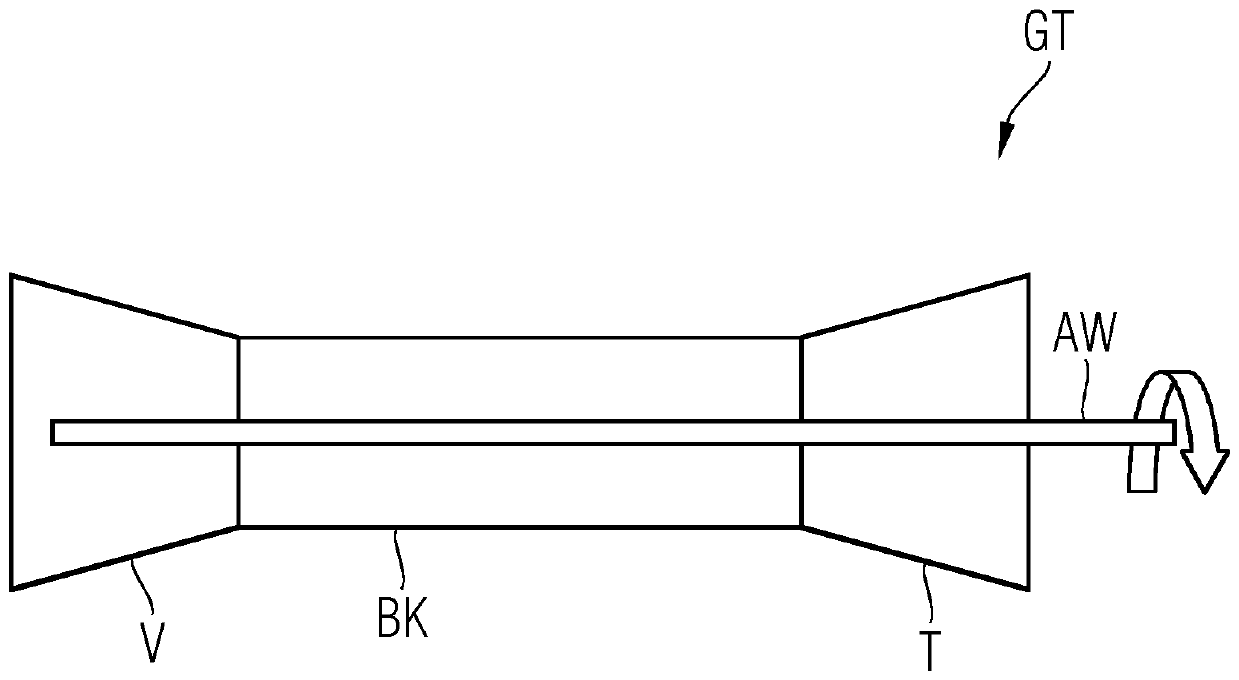
[0026] figure 1 As an application example of the invention, a gas turbine GT is shown in the schematic diagram with a combustion chamber BK in which it is necessary to measure the gas temperature distribution during operation. The gas turbine GT has a compressor V for compressing incoming air, a combustor BK for combusting delivered fuel, and a turbine T for converting heat and kinetic energy generated by combustion into rotational energy. Rotational energy is also transmitted via the drive shaft AW to the compressor V in order to drive it.

[0027] Furthermore, the invention is also used for measuring the gas temperature distribution in the combustion chamber of an internal combustion engine, a jet propulsion plant or other internal combustion engines.

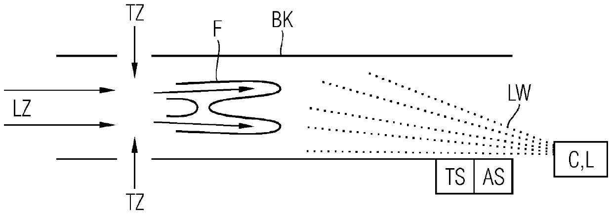
[0028] figure 2 The schematic diagram shows a tubular combustion chamber BK with an optical sensor C for measuring the gas temperature distribution in the combustion chamber BK. The combustion chamber BK can be, in partic...


PUM


Abstract

An optical sensor (C) directed into a combustion chamber (BK) is used to selectively sense a predefined spectral range of an optical spectrum for different light paths (LW) running through the combustion chamber (BK) to measure a gas temperature distribution in the combustion chamber (BK). A spectral intensity (SI) is determined for each spectral range and associated with an item of light path information (LA) which identifies the light path (LW) in question. The spectral intensities (SI) determined and the associated items of light path information (LA) are fed as input data to a machine learning routine (NN) which is trained to reproduce spatially resolved training temperature distributions (TTD). Output data from the machine learning routine (NN) are then output as the gas temperature distribution (GTD).

Description

technical field [0001] In combustion chambers, in particular of internal combustion engines, the combustion process often takes place at very high temperatures, pressures and / or flow velocities. In gas turbines, for example, temperatures of about 1300-2000° C., pressures of about 15-25 bar and flow velocities of about 300 m / s occur. In order to optimize the construction and operation of the internal combustion engine, in particular with regard to its efficiency, exhaust gas emissions and / or wear, it is extremely advantageous to detect and evaluate information about the temperature distribution in the combustion chamber. If it happens that local temperature peaks frequently lead to higher NOx emissions and higher wear, it is extremely advantageous here not only to detect the temperature mean value, but also in particular to detect inhomogeneities or inhomogeneous distributions of the gas temperature measure. Background technique [0002] Under the aforementioned physical am...

Claims


Application Information

Patent Timeline
Patent Type & Authority Applications(China)
IPC IPC(8): F02D41/14G01J5/00G01J5/60G01J5/04
CPCG01J5/0014G01J5/0088G01J5/047F02D41/1447G01J5/602G01J2005/0077F05D2270/8041G01J5/60F02D41/1405F02D35/022F02D35/026F02D2041/1433G01J5/0896G01J3/42G01J5/58G01J5/0806G01J5/0808G01J5/80G01M15/14G01J5/0802
Inventor H-G.布鲁梅尔K.黑舍V.施特尔青格
Owner SIEMENS AG
Why Eureka
Try Eureka