Antennaless wireless device

A wireless device, no antenna technology, applied in the antenna grounding device, antenna support/installation device, antenna, etc., can solve the problems of insufficient performance of antenna elements and inability to excite radiation patterns.

Inactive Publication Date: 2011-07-06
FRACTUS
View PDF9 Cites 6 Cited by
  • Summary
  • Abstract
  • Description
  • Claims
  • Application Information

AI Technical Summary

Problems solved by technology

This is evident from the fact that no radiative mode can be excited on the ground plane layer due to the fact that the ground plane layer is electrically shorted (i.e., its size is much smaller than the wavelength) at the frequency of operation
[0020] Under this limitation, although the performance of wireless portable devices may be sufficient to receive electromagnetic wave signals (such as those of broadcasting services), the antenna elements cannot provide sufficient performance for cell phone communication standards that also require the transmission of electromagnetic wave signals (for example, in terms of input return loss or gain)

Method used


Image

  • Antennaless wireless device
  • Antennaless wireless device
  • Antennaless wireless device

Examples


Embodiment Construction

[0151] Further features and advantages of the present invention will become apparent with reference to the following detailed description of some preferred embodiments. The detailed description of some preferred embodiments of the present invention with reference to the accompanying drawings is given for the purpose of illustration only and is by no means meant to limit the meaning of the present invention.

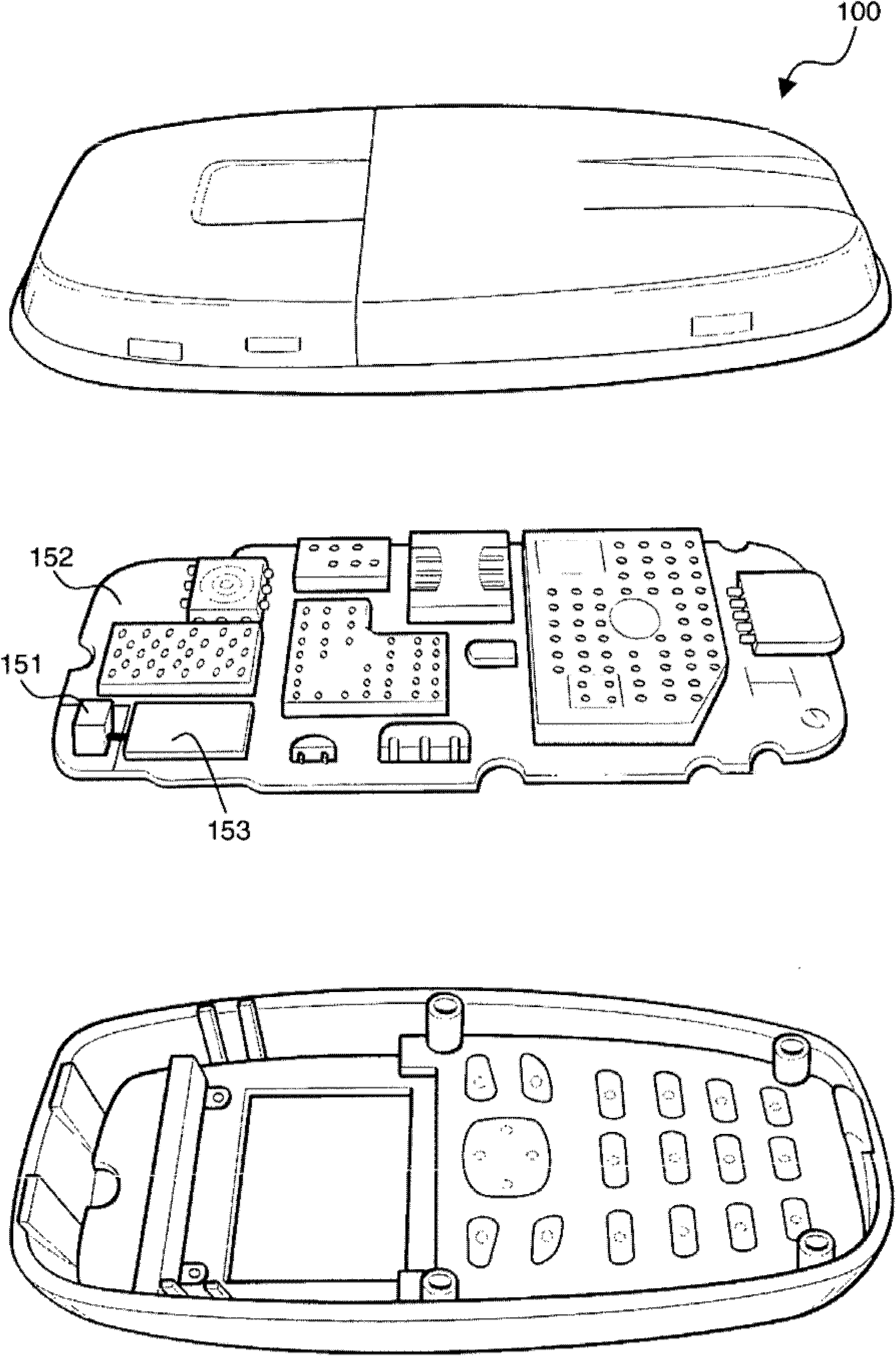
[0152] FIG. 1 shows an illustrative example of an antennaless wireless handheld or portable device 100 in accordance with the present invention. exist Figure 1a , an exploded perspective view of an antennaless wireless handheld or portable device 100 is shown, which includes a radiating structure including a radiating booster 151 and a ground plane layer 152 (which may be included in the layers of a multilayer PCB) . The antennaless wireless handheld or portable device 100 also includes a radio frequency system 153, which is interconnected with the radiating structure....


PUM


Abstract

The invention refer to an antennaless wireless handheld or portable device (100) comprising: a user interface module (101), a processing module (102), a memory module (103), a communication module (104) and, a power management module (105); the communication module (104) including a radiating system (200) capable of transmitting and receiving electromagnetic wave signals in a first frequency region; said radiating system (200) comprising a radiating structure (201) comprising or consisting of at least one ground plane layer (206) including a connection point (207), at least one radiation booster (204) including a connection point (205) and an internal port (208), wherein the internal port (208) is defined between the connection point (205) of the at least one radiation booster (204) and the connection point (207) of the at least one ground plane layer (206); wherein a ground plane rectangle (450) is defined as being the minimum-sized rectangle that encompasses the at least one ground plane layer (206, 402), so that the sides of the ground plane rectangle (450) are tangent to at least one point of the at least one ground plane layer (206, 402), wherein the ratio between a side of the ground plane rectangle (450) and the free-space wavelength corresponding to the lowest frequency of the first frequency region is larger than 0.1 such that the ground plane layer supports a radiation mode; wherein the at least one radiation booster (204) couples the electromagnetic energy from the radiofrequency system (202) to the ground plane layer (206) in transmission, and from the ground plane layer (206) to the radiofrequency system (202) in reception; wherein the at least one radiation booster (204) has a maximum size smaller than 1 / 30 times the free-space wavelength corresponding to the lowest frequency of the first frequency region; the radiating system (200) further comprising a radiofrequency system (202), and an external port (203).

Description

technical field [0001] The present invention relates to wireless handheld devices, in particular to wireless portable devices that require transmission and reception of electromagnetic wave signals. Background technique [0002] Wireless handheld or portable devices typically run one or more cellular communication standards and / or wireless connectivity standards, each assigned to one or more frequency bands contained within one or more regions of the electromagnetic spectrum. within an area. [0003] For this purpose, a certain space within the wireless handheld or portable device is usually dedicated to integrating the radiating system. However, the radiation system is desirably small in order to occupy as little space as possible inside the device, which then allows to obtain a smaller device, or to add more special devices and functions to the device. At the same time, it is sometimes required that the radiation system be flat, since this allows obtaining a slim device,...

Claims


Application Information

Patent Timeline
Patent Type & Authority Applications(China)
IPC IPC(8): H01Q1/24H01Q9/02H01Q5/00H01Q5/335
CPCH01Q1/243H01Q5/00H01Q5/0041H01Q5/335H01Q5/35H01Q5/50H01Q1/48H01Q1/50H01Q9/0407H05K999/99
Inventor 乔米·安古拉奥萝拉·安杜哈尔卡勒斯·普恩特约瑟普·蒙布鲁
Owner FRACTUS
Why Eureka
Try Eureka