Infusion pump module

A technology for infusion pumps and pump units, which can be used in pressure infusion, flow monitors, hypodermic injection devices, etc., and can solve the problems of large size and limited selection of system installation places

Inactive Publication Date: 2011-07-13
RICOH KK
View PDF4 Cites 9 Cited by
  • Summary
  • Abstract
  • Description
  • Claims
  • Application Information

AI Technical Summary

Problems solved by technology

As a result, the size of the system is relatively large, which limits the choice of where the system can be installed

Method used


Image

  • Infusion pump module
  • Infusion pump module
  • Infusion pump module

Examples


Embodiment Construction

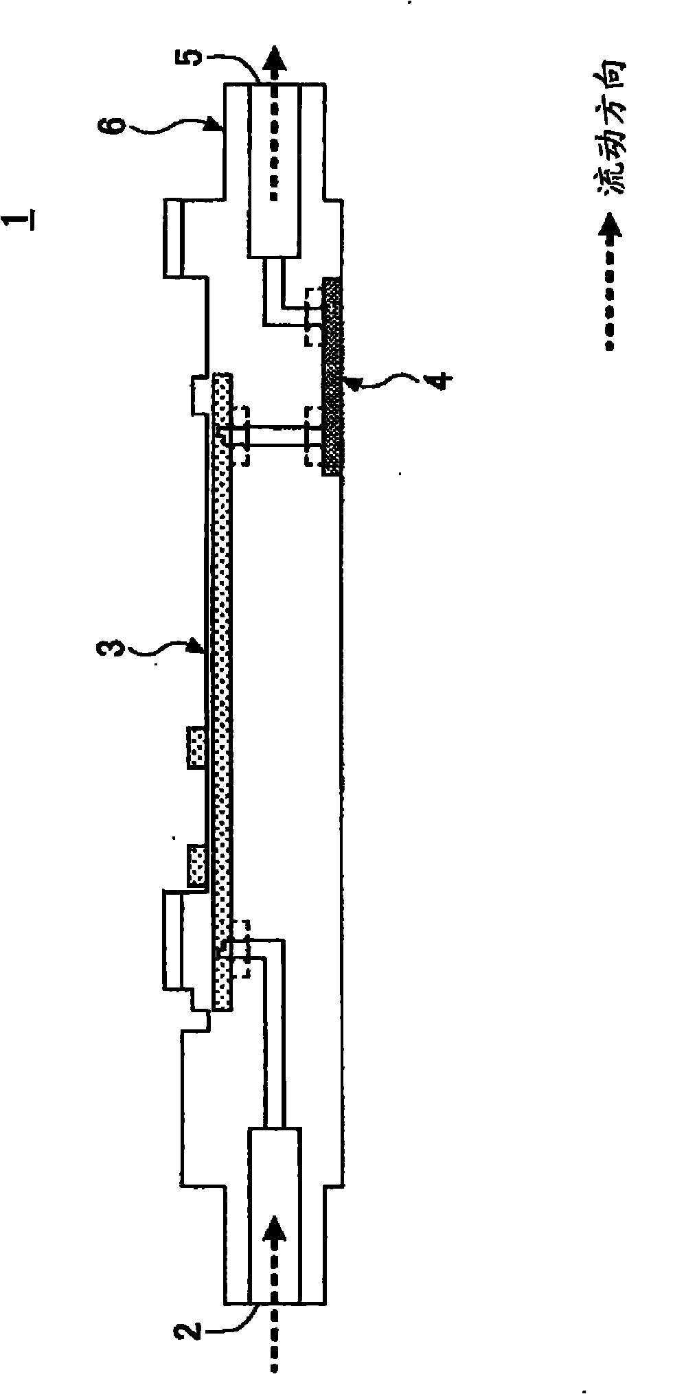
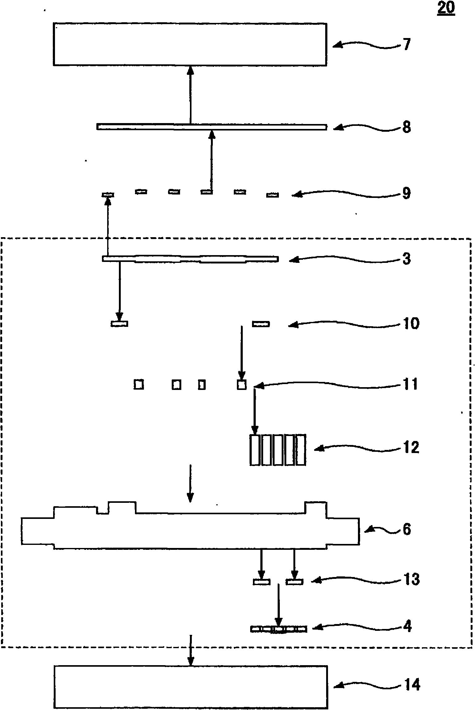
[0018] Hereinafter, embodiments for realizing the present invention will be described with reference to the accompanying drawings. Next, the configuration of the flow channel of the infusion pump module according to the embodiment will be described. figure 1 is a schematic diagram showing the configuration of the main part 1 of the infusion pump module. Such as figure 1 As shown in , the main components 1 of the infusion pump module include a fluid inlet 2 , a pump 3 , a flow sensor 4 , a fluid outlet 5 and a main body 6 . In the infusion pump module, the fluid flowing in through the fluid inlet 2 is delivered by the pump 3 to the flow sensor 4 for flowing out through the fluid outlet 5 . The pump 3 includes piezoelectric elements. A voltage having a predetermined frequency is applied to the piezoelectric element to cause vibration, thereby exerting a pumping function.

[0019] Such as figure 1 As shown, the pump 3 and the flow sensor 4 are placed facing each other, with ...


PUM


Abstract

An infusion pump module for transferring fluid includes a fluid inlet part having an inlet to receive the fluid, a fluid outlet part having an outlet to discharge the fluid, a pump unit having a piezoelectric element, and a flow rate sensor to measure a flow rate of the fluid flowing inside the module, wherein the fluid inlet part, the fluid outlet part, the pump unit, and the flow rate sensor are connected together to cause the fluid received by the fluid inlet part to be discharged from the fluid outlet part, and the fluid inlet part, the fluid outlet part, the pump unit, and the flow rate sensor connected together form a single continuous flow channel.

Description

technical field [0001] The present disclosure generally relates to an infusion pump module provided with a flow sensor to measure the flow of fluid to be delivered. Background technique [0002] In medical procedures, for example, medical solutions for infusion into patients need to be delivered. For this purpose, a fluid transfer pump module is used which includes a piezoelectric element-based pump and an oscillation circuit for driving the piezoelectric element (see, for example, Japanese Patent Application Laid-Open No. 8-303352). In such a fluid transfer pump, a voltage signal having a predetermined frequency is applied to vibrate a piezoelectric element, thereby pushing a medical solution in a flow channel for fluid transfer. [0003] In addition, a flow sensor is connected to a fluid conduit, such as a tube connected to a fluid transfer pump, to control the oscillating circuit based on the flow measured by the flow sensor. This allows control of the fluid flow to be ...

Claims


Application Information

Patent Timeline
Patent Type & Authority Applications(China)
IPC IPC(8): A61M5/142
CPCA61M5/16804A61M5/142A61M5/14212A61M5/16886
Inventor 友山贵嗣鎌田照己杉本泰规
Owner RICOH KK
Why Eureka
Try Eureka