Decompression device of internal combustion engine

a technology of decompression device and internal combustion engine, which is applied in the direction of machines/engines, valve arrangements, mechanical equipment, etc., can solve the problems of large time occupied by replacement, real trouble, and difficulty in setting the speed of decompression operating engine exactly at the desired valu

Active Publication Date: 2005-05-24
KAWASAKI MOTORS LTD
View PDF2 Cites 9 Cited by
  • Summary
  • Abstract
  • Description
  • Claims
  • Application Information

AI Technical Summary

Benefits of technology

[0009]The present invention addresses the above objectives and a scope of the present invention is to provide a decompression device of an internal combustion engine which can be arranged compactly and can extend conditions on which a decompression is activated.

Problems solved by technology

Therefore, the replacement takes up a large amount of time and is really troublesome.
Thus, it is difficult to set the decompression operating engine speed exactly at a desired value.
(4) The centrifugal-weight type decompression device only allows a control based on the decompression operating engine speed which is preset when it is assembled, and it cannot perform a control depending on other engine speed conditions.
That is, the device cannot function appropriately, for example, in the case where it is used at the time of a stop operation of an internal combustion engine and when a decompression is desired to be performed at an engine speed higher than the idling engine speed, or otherwise when a decompression is not desired to be performed until stop of the engine.

Method used


Image

  • Decompression device of internal combustion engine
  • Decompression device of internal combustion engine
  • Decompression device of internal combustion engine

Examples


Embodiment Construction

[0030]The present invention will now be described in detail referring to the accompanying drawings illustrating the embodiment thereof.

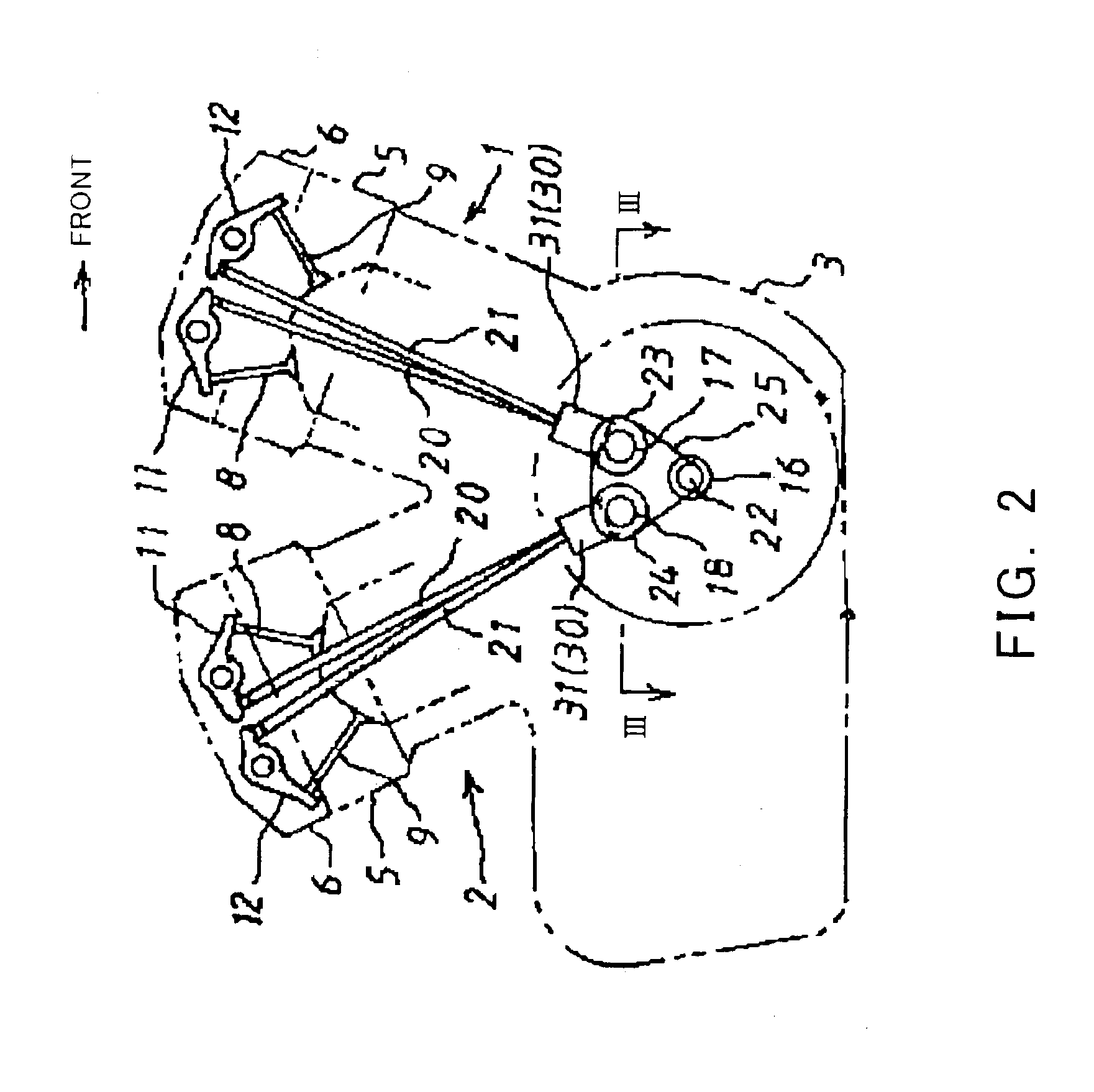
[0031]ENTIRE INTERNAL COMBUSTION ENGINE AND VALVE MECHANISM THEREOF—FIG. 2 shows a schematic of a V-twin type internal combustion engine for motorcycles to which an embodiment of the present invention is applied, and its intake and exhaust valve mechanism. The internal combustion engine shown by the phantom lines in FIG. 2 typically comprises a first cylinder 1 (also referred to as “a front cylinder”) tilted forward and a second cylinder 2 (also referred to as “a rear cylinder”) tilted rearward, both arranged above a crank case 3. A cylinder head 5 of each of the cylinders 1 and 2 is provided with intake valve(s) 8 and exhaust valve(s) 9. Rocker arms 11 and 12 are arranged within a head cover 6, which covers the cylinder head 5, so as to engage with the intake valve(s) 8 and the exhaust valve(s) 9, respectively.

[0032]A cam shaft 17 for the first cyli...


PUM


Abstract

A decompression device of an internal combustion engine which is arranged compactly with reduced number of parts is provided. Typically, the device comprises a push-up rod which is disposed on a circumference of a cam shaft of the engine, within a range in the circumferential direction corresponding to a compression stage of the engine, and which protrudes outwardly in the radial direction of the cam shaft with respect to a base face of an exhaust-side cam face. The push-up rod is supported movably in the cam shaft direction between a decompression operating position, at which the push-up rod is inserted into a width-wise range of a bottom face of an exhaust-side tappet and a decompression non-operating position, at which the push-up rod is retreated from the width-wise range of the bottom face. Moreover, in the case of a multi-cylinder internal combustion engine having two cam shafts, a common solenoid is interlocked with the push-up rods provided on both the cam shafts and, thus the single solenoid can decompress the cylinders.

Description

TECHNICAL FIELD[0001]The present invention relates to a decompression device of an internal combustion engine, which can improve performance of the engine, for example, during start-up, by extracting compression pressure inside a combustion chamber at a compression stage of the engine.BACKGROUND OF THE INVENTION[0002]One type of conventional decompression device of an internal combustion engine is a centrifugal-weight type decompression device, such as is disclosed in Japanese Examined Patent Application Publication No. H02-25007. In this decompression device of centrifugal-weight type, as shown in FIG. 1, a plurality of centrifugal weights 103 and 104, which open outwardly in the radial direction of a cam shaft 101 by a centrifugal force, are swingably attached in an end portion of the cam shaft 101. The cam shaft 101 includes an exhaust-side cam face 110. One of the centrifugal weights 104 is provided with a decompression cam portion 105. Both the centrifugal weight 103 and 104 ar...

Claims


Application Information

Patent Timeline
Patent Type & Authority Patents(United States)
IPC IPC(8): F01L13/08
CPCF01L1/022F01L13/08F01L2820/032F01L2001/0537F01L13/085
Inventor HIRAGA, TAKASHI
Owner KAWASAKI MOTORS LTD
Why Eureka
Try Eureka