Refrigerant cycle device

a cycle device and refrigerant technology, applied in the direction of refrigeration components, indirect heat exchangers, lighting and heating apparatus, etc., can solve the problems of increased charge of refrigerant, difficult handling of materials, and difficulty in using these compounds as refrigerants, and achieve the effect of reducing the pressure of refrigeran

Active Publication Date: 2008-10-09
SAMSUNG ELECTRONICS CO LTD
View PDF3 Cites 9 Cited by
  • Summary
  • Abstract
  • Description
  • Claims
  • Application Information

AI Technical Summary

Benefits of technology

[0016]Therefore, it is an aspect of the invention to provide a refrigerant cycle device which can prevent inflow of a liquid refrigerant into a compressor and can be manufactured compactly.
[0017]It is another aspect of the invention to provide a refrigerant cycle device using carbon dioxide as a refrigerant, which can reduce noise and improve reliability.
[0018]It is yet another aspect of the invention to provide a refrigerant cycle device which can improve heat exchange efficiency.
[0035]The refrigerant cycle device may further comprise an orifice to decrease a pressure of the refrigerant flowing through the second passage.
[0038]In accordance with yet another aspect of the invention, there is provided a refrigerant cycle device comprising: a compressor; a gas cooler; a pressure reducing device; an evaporator, the compressor, the gas cooler, the pressure reducing device and the evaporator being in fluid communication to form a closed loop; and a heat exchanger to heat-exchange a refrigerant discharged from the gas cooler and a refrigerant discharged from the evaporator. The heat exchanger is a double pipe heat exchanger including a first refrigerant pipe, a second refrigerant pipe surrounding the first refrigerant pipe, and an orifice defined by the first refrigerant pipe and the second refrigerant pipe to decrease a pressure of the refrigerant flowing between the first refrigerant pipe and the second refrigerant pipe.

Problems solved by technology

However, because freon discharged in the atmosphere causes problems of global warming, disruption of the ozone layer and the like, there has been research related to the use of a natural refrigerant having little influence on the environment, e.g., oxygen (O2), carbon dioxide (CO2), hydrocarbon (HC), ammonia (NH3), or water (H2O) as a refrigerant.
Of the above natural refrigerants, because oxygen and water have low pressure, it is difficult to use these compounds as a refrigerant.
Because ammonia and hydrocarbon are combustible, these materials are difficult to handle.
However, the conventional refrigerant cycle device has problems such that the charging amount of refrigerant is increased due to the installation of the accumulator and the refrigerant cycle device cannot be made compact.
However, if a large amount of surplus liquid refrigerant is included in the refrigerant flowing through the evaporator because a temperature around the evaporator is low, the inflow of the liquid refrigerant into the compressor cannot be perfectly prevented by the constitution such that the refrigerant from the evaporator flows from up to down in the low pressure side passage.
Also because the refrigerant in the high pressure side passage flows from down to up, the liquid refrigerant flowing to the expansion valve is evaporated, and flash gas is generated, which causes deterioration of the performance of the expansion valve.
Further, because a first refrigerant pipe and a second refrigerant pipe of the internal heat exchanger are spaced apart from each other, when the refrigerant flows through the internal heat exchanger or when vibration by the operation of the compressor is transmitted, the first refrigerant pipe of the internal heat exchanger vibrates to be contacted with the second refrigerant pipe, thereby generating noise.
If the first and second refrigerant pipes get worn by the successive contact, operational reliability of the refrigerant cycle device is deteriorated.
To fulfill such a requirement, a length of the double pipe type internal heat exchanger should be increased, which results in increase in cost of the internal heat exchanger.
There is also a limitation in improving the performance of the refrigeration cycle due to the insufficient heat exchange.

Method used


Image

  • Refrigerant cycle device
  • Refrigerant cycle device
  • Refrigerant cycle device

Examples


first embodiment

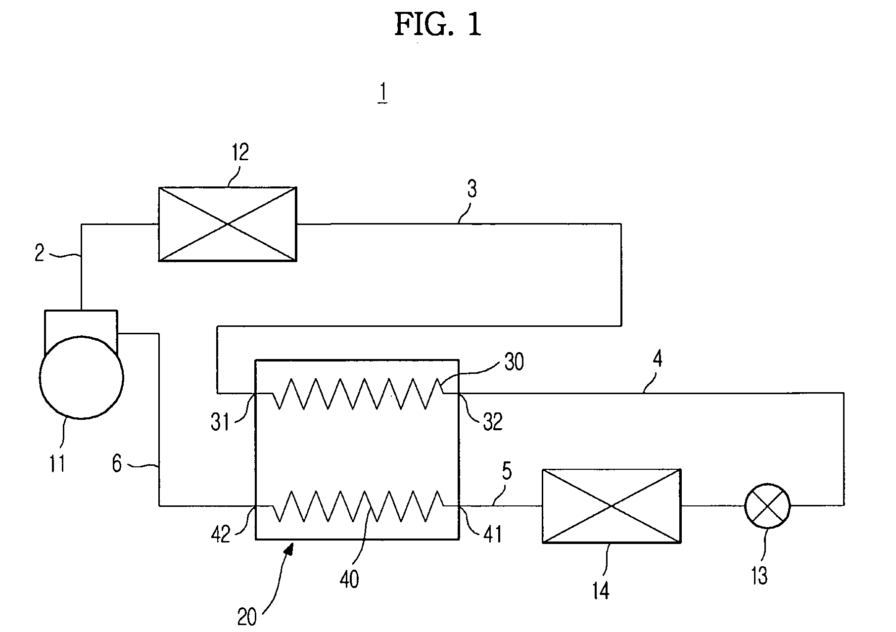
[0052]FIG. 1 is a refrigerant circuit diagram of a refrigerant cycle device in accordance with the present invention.

[0053]A refrigerant cycle device according to the embodiment of the present invention is used in an air conditioner, a refrigerator, a display case, or the like.

[0054]As shown in FIG. 1, a refrigerant cycle device 1 according to the first embodiment of the present invention is constituted such that a compressor 11, a gas cooler 12, an expansion valve 13 (pressure reducing device), and an evaporator 14 are connected to each other in a closed loop.

[0055]The compressor 11 is provided between the gas cooler 12 and the evaporator 14. The compressor 11 compresses a gas refrigerant of a low temperature and a low pressure into a gas refrigerant of a high temperature and a high pressure. Various types of compressors, such as a hermetic reciprocating compressor, a rotary compressor, a scroll compressor or the like, can be used.

[0056]An inlet of the gas cooler 12 is connected wi...

second embodiment

[0093]Hereinafter, a refrigerant cycle device according to the present invention will be described.

[0094]The same elements as the first embodiment are denoted by the same reference numerals, and a detailed explanation thereof is omitted.

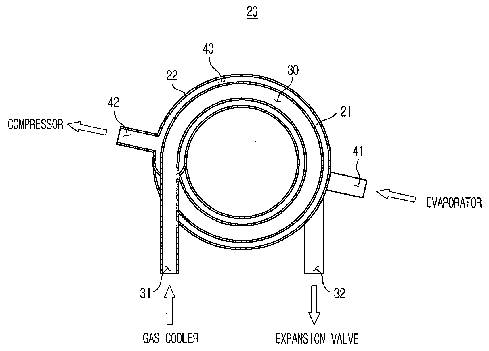
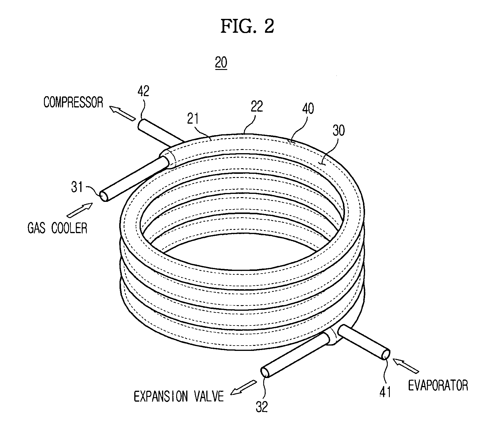
[0095]FIG. 5 is a schematic perspective view illustrating a connecting structure of a heat exchanger and an evaporator in a refrigerant cycle device according to a second embodiment of the present invention.

[0096]A heat exchanger of the refrigerant cycle device according to the second embodiment is generally the same as the heat exchanger of the refrigerant cycle device according to the first embodiment.

[0097]However, the evaporator 14 and the heat exchanger 20 are arranged such that the outlet of the evaporator 14 is provided at a higher position than the inlet 41 of the second passage 40 of the heat exchanger 20. Specifically, the evaporator 14 and the heat exchanger 20 are arranged such that the outlet of the evaporator 14 is positioned at the sub...

third embodiment

[0100]Hereinafter, a refrigerant cycle device according to the present invention will be described.

[0101]The same elements as the second embodiment are denoted by the same reference numerals, and the detailed explanation thereof is omitted.

[0102]FIG. 6 is a schematic perspective view illustrating a connecting structure of a heat exchanger and an evaporator in a refrigerant cycle device according to a third embodiment of the present invention, and FIG. 7 is a schematic sectional view of the heat exchanger shown in FIG. 6.

[0103]As shown in FIGS. 6 and 7, a heat exchanger 50 of this embodiment is formed in a double pipe type, and has a substantially rectangular helical structure. In order for the heat exchanger 50 to have a rectangular helical structure, the heat exchanger 50 is formed with bent portions 53 which are bent with a predetermined interval therebetween.

[0104]By the above configuration of bending the heat exchanger 50, double pipe type first and second refrigerant pipes 51 a...


PUM


Abstract

A refrigerant cycle device capable of preventing inflow of a liquid refrigerant into a compressor and having a compact structure is disclosed. The refrigerant cycle device includes a compressor, a gas cooler, a pressure reducing device, an evaporator, and a heat exchanger to heat-exchange a refrigerant discharged from the gas cooler and a refrigerant discharged from the evaporator. The heat exchanger includes a first passage connected to an outlet of the gas cooler and a second passage connected to an outlet of the evaporator. The refrigerant in the first passage flows downward, and the refrigerant in the second passage flows upward.

Description

CROSS-REFERENCE TO RELATED APPLICATIONS[0001]This application claims the benefit of Korean Patent Applications No. 10-2007-0034442, filed on Apr. 6, 2007 and 10-2007-0034443, filed on Apr. 6, 2007 in the Korean Intellectual Property Office, the disclosures of which are incorporated herein by reference.BACKGROUND[0002]1. Field[0003]The present invention relates to a refrigerant cycle device, and more particularly to a refrigerant cycle device in which carbon dioxide is used as a refrigerant.[0004]2. Description of the Related Art[0005]A conventional refrigerant cycle device includes a refrigerant cycle configured such that a compressor, a gas cooler, a pressure reducing device (e.g., expansion valve) and an evaporator are sequentially pipe-connected to each other in a closed loop.[0006]Freon (R11, R12, R134a, etc.) has been commonly used as a refrigerant of a refrigerant cycle device. However, because freon discharged in the atmosphere causes problems of global warming, disruption of...

Claims


Application Information

Patent Timeline
Patent Type & Authority Applications(United States)
IPC IPC(8): F25B41/00F25B41/06
CPCF25B40/00F25B2309/061F25B2500/01F28D7/022F28D7/14
Inventor YAMANAKA, MASAJICHO, SUNG OUG
Owner SAMSUNG ELECTRONICS CO LTD
Why Eureka
Try Eureka