
Method for moulding female end of heavy caliber socket reinforced concrete pipe

A forming method and socket end technology, which is applied in the direction of reinforced forming, ceramic forming machine, manufacturing tools, etc., can solve the problems affecting the accuracy, error, and inability to meet the accuracy requirements of large-diameter reinforced concrete pipes, and achieve the effect of ensuring the forming accuracy

Active Publication Date: 2011-07-13
SHANGHAI URBAN CONSTRUCTION MUNICIPAL ENGINEERING (GROUP) CO LTD
View PDF6 Cites 11 Cited by
  • Summary
  • Abstract
  • Description
  • Claims
  • Application Information

AI Technical Summary

Problems solved by technology

Since the socket end needs to be equipped with a steel collar, and when the roundness and precision of the steel collar meet the requirements after expansion, due to the large diameter and relatively thin thickness, deformation will inevitably occur during the hoisting process, resulting in Its roundness is reduced and errors occur, which in turn affects the precision after molding
At present, the existing molds cannot effectively correct the roundness of the steel collar before pouring, and cannot meet the accuracy requirements of large-diameter reinforced concrete pipes, and the larger the diameter, the greater the absolute error. Therefore, in the manufacturing process of large-diameter socket-type reinforced concrete pipes There is a need for a mold that can correct the roundness of steel collars

Method used


Image

  • Method for moulding female end of heavy caliber socket reinforced concrete pipe
  • Method for moulding female end of heavy caliber socket reinforced concrete pipe
  • Method for moulding female end of heavy caliber socket reinforced concrete pipe

Examples


Embodiment Construction

[0026] The features of the utility model and other relevant features are further described in detail below in conjunction with the accompanying drawings through the embodiments, so as to facilitate the understanding of those skilled in the art:

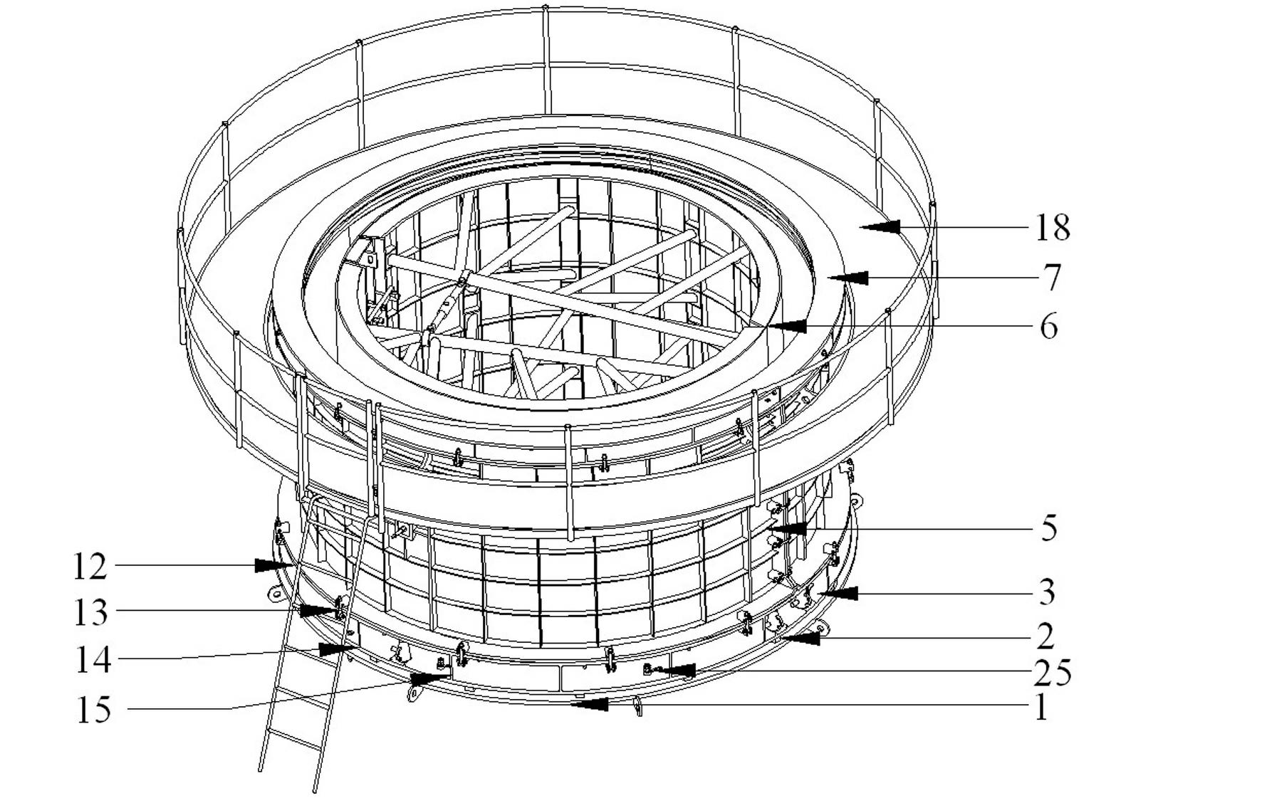
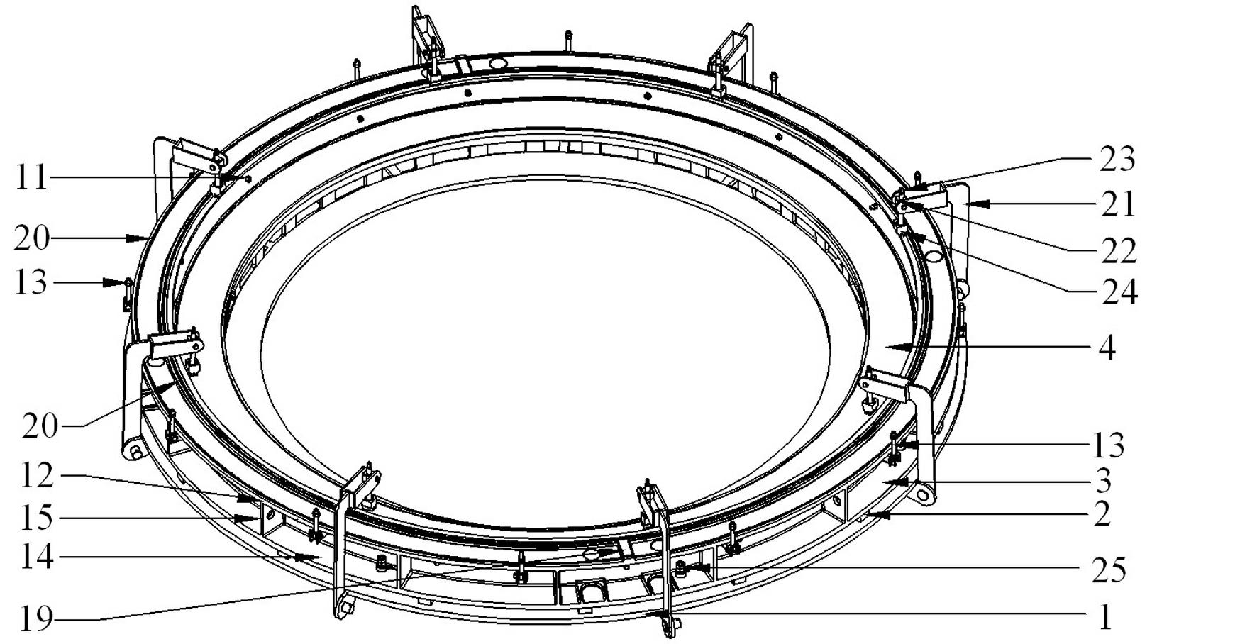
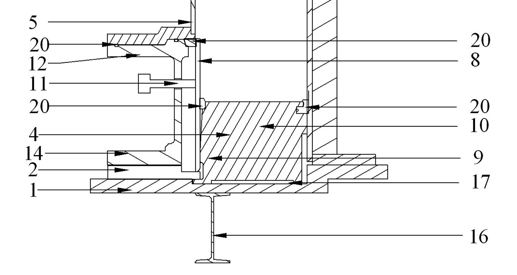
[0027] Such as Figure 1 to Figure 3 As shown, the total reference numerals 1-25 represent respectively: bottom mold 1, cushion block 2, lower mold 3, positioning support 4, middle mold 5, inner mold 6, upper mold 7, steel collar 8, cylinder part 9 , cone part 10, positioning hole 11, flange 12, closing bolt 13, flange 14, reinforcing rib 15, I-beam 16, annular groove 17, operating platform 18, raised strip 19, slurry stop rubber Bar 20, rotating rod 21, crosshead 22, press down screw rod 23, pressure head 24, handle 25.

[0028] see figure 1 As shown, the reinforced concrete pipe mold in the present invention is mainly composed of bottom mold 1, lower mold 3, middle mold 5, upper mold 7 and inner mold 6, wherein upper mold 7 is a c...


PUM


Abstract

The invention relates to a concrete pipe joint die, in particular to a method for moulding a female end of a heavy caliber socket reinforced concrete pipe. The method comprises the following steps of: placing a bottom die on the ground and leveling, and coaxially arranging a positioning support; sleeving a steel ring of the female end in a lower die, and connecting the lower die with the steel sleeve ring; hoisting the lower die and the steel ring onto the bottom die, and cancelling the connection between the lower die and the steel sleeve ring; coaxially connecting the lower die and the bottom die, and sleeving the steel sleeve ring on the positioning support; adjusting a screw on the lower die to adjust the circular degree of the steel sleeve ring; arranging a middle die on a flange; arranging an upper die on the middle die; and arranging an inner die and pouring a concrete structure. The method has the advantages that: the shape of the bottom of the steel sleeve ring at the female end is restrained by the cylinder on the positioning support, and the shape of the end part of the steel sleeve ring at the female end is regulated by rotating the screw in a positioning hole to ensure the moulding accuracy of the steel sleeve ring.

Description

technical field [0001] The invention relates to a concrete pipe joint mold, in particular to a forming method for the socket end of a large-diameter socket-type reinforced concrete pipe. Background technique [0002] Concrete pipes are widely used in jacking construction, and are generally used in areas where it is difficult to slot, have high requirements for the construction environment, and cannot cause ground subsidence under specific geographical conditions, such as railways, highways, etc. Underground construction under objects. At present, the main structure of reinforced concrete pipes used in jacking method construction is: a steel cage is embedded in the concrete pipe wall, and the steel cage is assembled by two coaxial cylindrical steel skeletons through erecting steel bars. One end of the wall is fixed with a steel collar as a socket, and the other end of the concrete pipe wall is grooved outside as a socket, and the connection between the two concrete pipes is ...

Claims


Application Information

Patent Timeline
Patent Type & Authority Applications(China)
IPC IPC(8): B28B21/02B28B21/58
Inventor 田培云居贤镛桂植梁葛以衡顾利军朱林峰沈君华
Owner SHANGHAI URBAN CONSTRUCTION MUNICIPAL ENGINEERING (GROUP) CO LTD
Learn More