
Connection line binding machine

A technology for a wire tying machine and connecting wire, which is applied to the parts and packaging of the bundling machinery, and can solve the problems of low bundling efficiency, different wire coil standards, and uneven product packaging levels.

Active Publication Date: 2011-07-13
刘光辉
View PDF6 Cites 4 Cited by
  • Summary
  • Abstract
  • Description
  • Claims
  • Application Information

AI Technical Summary

Problems solved by technology

[0002]In the production process of various wires, it is usually necessary to wind the wires into rolls for bundling. The existing wires usually need to be bundled manually after being wound into rolls. Low efficiency; at the same time, due to the different proficiency and technology of each operator, the bundled wire coils have different standards, resulting in uneven product packaging levels

Method used


Image

  • Connection line binding machine
  • Connection line binding machine
  • Connection line binding machine

Examples


Embodiment Construction

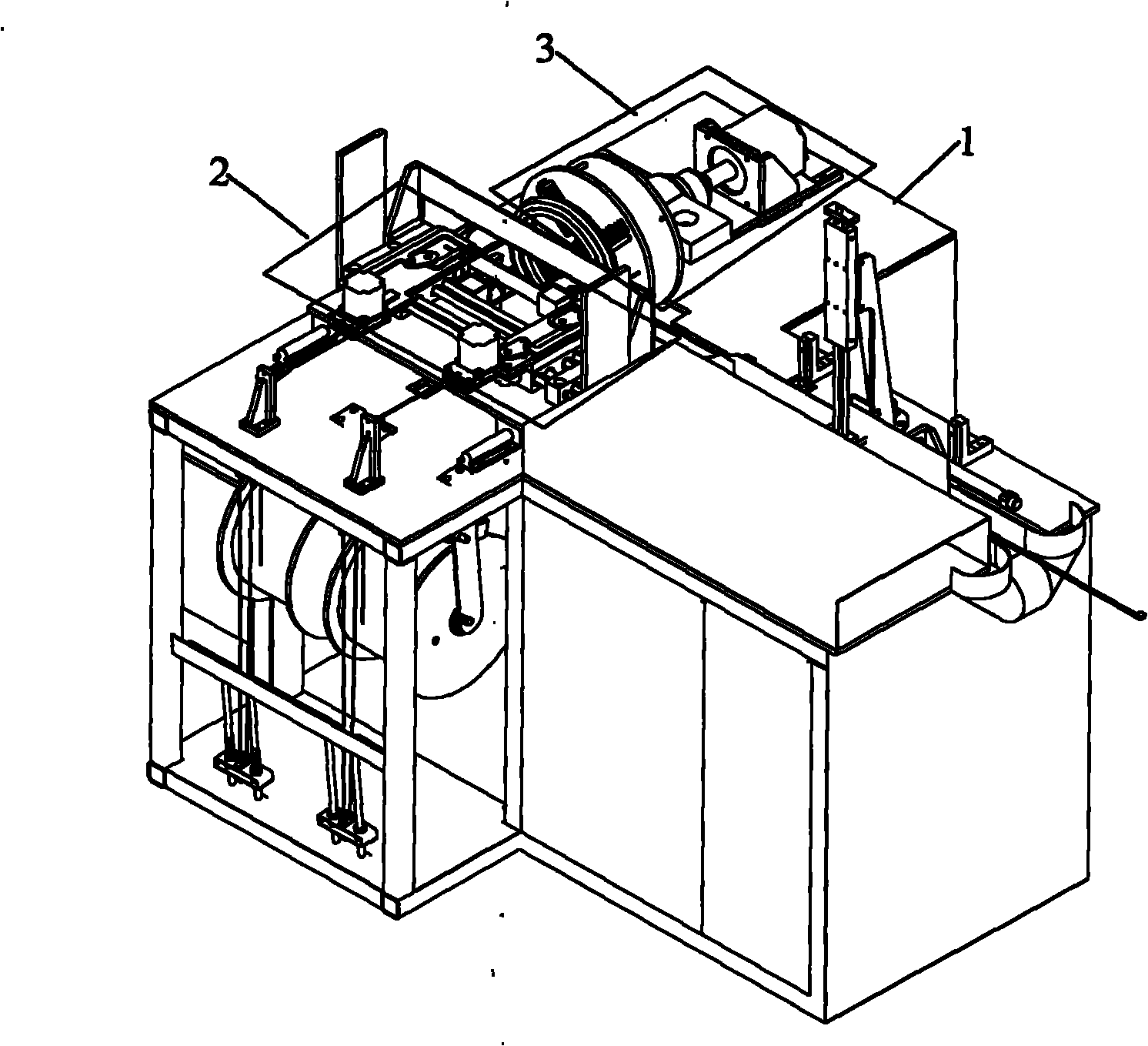
[0037] Such as figure 1 As shown, the present invention provides an embodiment of a connecting wire binding machine.

[0038] The connecting wire binding machine includes a frame 1, on which a winding device 3 and a binding device 2 are respectively arranged, and a circuit and an air circuit for controlling the coordinated work of the winding device 3 and the binding device 2 respectively. Road control device (not shown in the drawings).

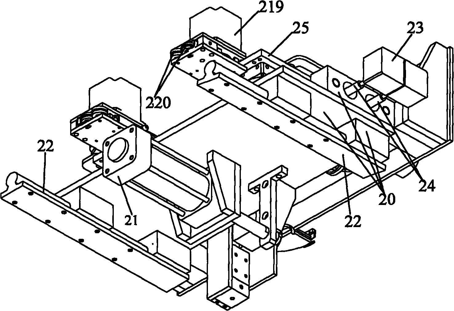
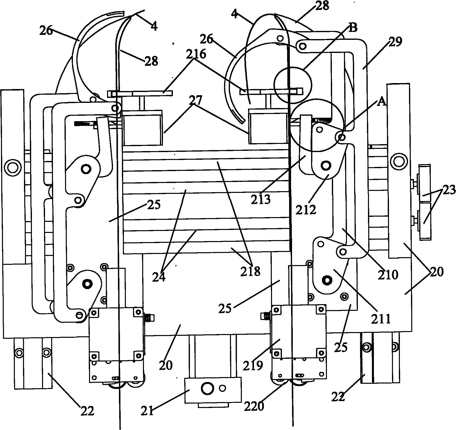
[0039] Such as figure 2 , image 3 , Figure 4 with Figure 5 As shown, the wire binding device includes two parallel guide rails 22 fixed to the frame 1 and a wire binding frame 20 slidingly matched with the guide rails 22, and the wire binding frame 20 is outputted with the wire binding cylinder 21 fixed on the frame 1. The end is fixed, and two mounting seats 25 are provided on the binding frame 20, and a swing cylinder (not shown in the accompanying drawings) that cooperates with the first connecting rod 211 is provided on the moun...


PUM


Abstract

The invention discloses a connection line binding machine. A frame is provided with a line winding device, a line binding device and control devices controlling the coordination operation of the devices respectively. The line binding device comprises two parallel guide rails and a line binding frame which is matched with the guide rails and provided with two mounting seats; each mounting seat is provided with an oscillating cylinder connected with a first connecting rod; the first connecting rod is connected with two transmission rods respectively; the middle parts of the transmission rods are connected with a second connecting rod respectively; the end parts of the two transmission rods are connected with a movable material gripping hand in a transmission manner; a static material gripping hand provided with an opening and matched with a line binding hand is arranged in a direction parallel to the dynamic material gripping hand; the line binding hand is fixed with a line binding motor fixed on the mounting seat; and the second connecting rod is provided with a drive rod connected with a line cutter. As the line binding device can completely and automatically bind the connection line, the connection line binding efficiency can be improved on one hand, and on the other hand, the line binding belt does not need to be cut into a certain length in advance, thereby avoiding waste of the line binding belt caused by pre-cutting.

Description

technical field [0001] The invention relates to the technical field of wire binding devices, in particular to a wire binding machine capable of automatically binding connecting wire harnesses. Background technique [0002] In the production process of various wires, it is usually necessary to wind the wires into rolls for bundling. The existing wires usually need to be bundled manually after being wound into rolls, and the bundling efficiency is low; at the same time, due to the different proficiency and technology of each operator , The bundled wire rolls have different standards, resulting in uneven product packaging levels. Contents of the invention [0003] The main technical problem to be solved by the present invention is to provide a connecting wire binding machine which can automatically bind the connecting wire harness. The connecting wire binding machine can improve the binding efficiency and reduce the labor cost. [0004] In order to solve the above problems, ...

Claims


Application Information

Patent Timeline
IPC IPC(8): B65B27/06B65B63/04B65B13/18B65B13/28
Inventor 刘光辉
Owner 刘光辉
Learn More