Belt type circulating dryer

A dryer and circulating fan technology, which is applied to dryers, drying, hearth furnaces, etc., can solve problems such as increased energy consumption, large airflow resistance, and uneven airflow in the material layer, so as to improve adaptability, The effect of uniformity improvement

Inactive Publication Date: 2011-07-13
JIANGSU MUYANG GRP CO LTD
View PDF5 Cites 9 Cited by
  • Summary
  • Abstract
  • Description
  • Claims
  • Application Information

AI Technical Summary

Problems solved by technology

[0005] 1. After the hot air is pushed by the circulating fan, it flows forward along the air distribution chamber under the conveyor belt, that is, flows along the width direction of the conveyor belt, and flows upward through the material layer at the same time. Due to the high flow rate of the hot air, it causes In the air distribution chamber, the wind pressure distribution along the width directio

Method used


Image

  • Belt type circulating dryer
  • Belt type circulating dryer
  • Belt type circulating dryer

Examples


Embodiment Construction

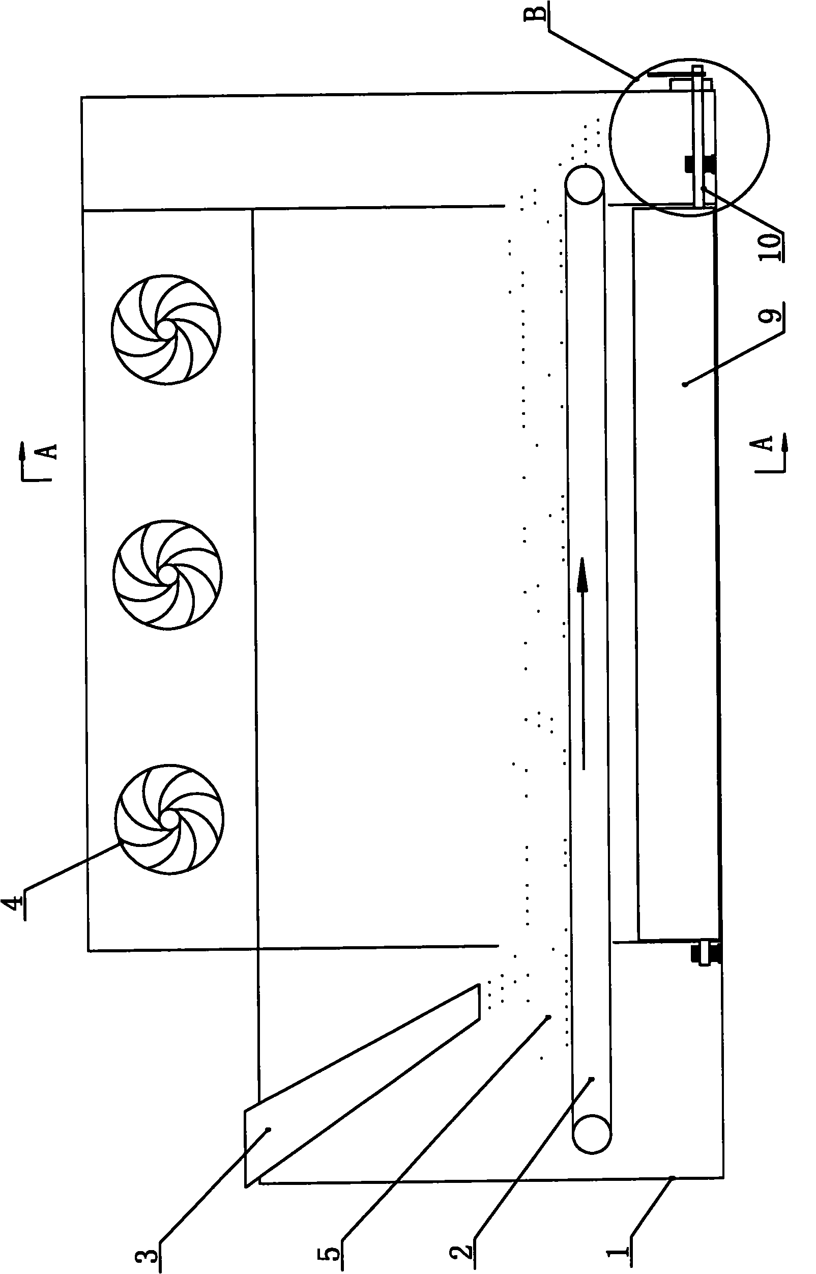
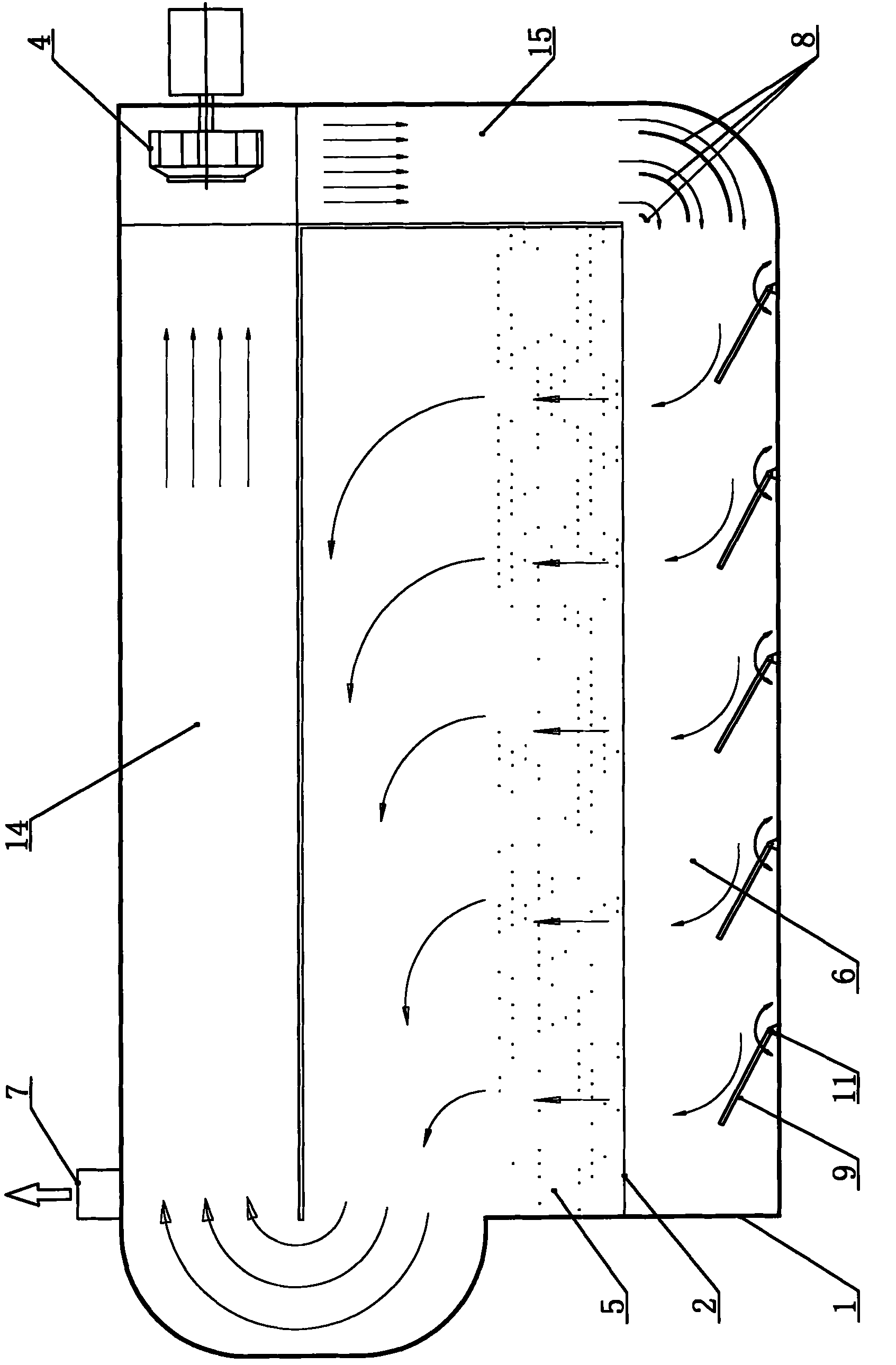
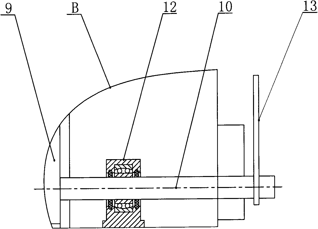
[0021] Such as figure 1 , figure 2 and image 3 As shown, the belt circulation dryer of the present invention comprises a body 1 and a conveyor belt 2 and a circulation fan 4 located in the body 1, the conveyor belt 2 is horizontally arranged, and one end of the conveyor belt 2 in the length direction is provided with a feed hopper 3, and the other One end is the discharge end, a material layer 5 is laid on the conveyor belt 2, and the air distribution chamber 6 is located below the conveyor belt 2. The hot air inlet of the air distribution chamber 6 is located at one end of the conveyor belt width direction, and the outlet air duct 15 of the circulating fan is vertically downward It communicates with the hot air inlet of the air distribution chamber 6, the air duct 14 of the suction port of the circulating fan communicates with the upper air duct of the material layer 5, and the top of the body is provided with an exhaust outlet 7.

[0022] The air distribution chamber 6 i...


PUM


Abstract

The invention discloses a belt type circulating dryer, which belongs to the technical field of feed processing machinery. A material layer is laid on a conveyor belt of the belt type circulating dryer. An air distribution chamber is formed below the conveyor belt. A hot air inlet of the air distribution chamber is positioned at one end of the width direction of the conveyor belt. An outlet air duct of a circulating fan is vertically downwards communicated with the hot air inlet of the air distribution chamber, and a suction mouth air duct of the circulating fan is communicated with an air duct above the material layer. A group of deflectors is arranged at a turning. The group of deflectors is arranged in the air distribution chamber, each deflector is extended along the length direction of the conveyor belt, and the deflectors are uniformly distributed along the width direction of the conveyor belt. Rotating shafts are arranged on each deflector respectively, and each rotating shaft is hinged to own rotating shaft pedestal respectively. Each rotating shaft pedestal is arranged on a bottom plate of the air distribution chamber. One end of the rotating shaft is extended out of a machine body, and an extended end is provided with an adjusting handle for adjusting an angle of the corresponding deflector. The belt type circulating dryer makes uniform a gas flow in a material, and ensures low gas flowing resistance and low energy consumption.

Description

technical field [0001] The invention relates to a dryer, in particular to a belt type circulation dryer, which belongs to the technical field of feed machinery. Background technique [0002] The belt circulation dryer in the prior art includes a machine body, a conveyor belt located inside the body, and a circulation fan. There is a material layer on the belt, and the air distribution chamber is below the conveyor belt. The hot air inlet of the air distribution chamber is located at one end of the conveyor belt width direction. The air duct of the suction port is connected with the upper air duct of the material layer. [0003] The material layer advances with the conveyor belt, and the air heated by the heater is blown vertically from the lower part of the conveyor belt under the drive of the circulating fan. The resistance of the material causes a pressure difference between the upper and lower layers of the material layer, and the pressure difference allows high-temperat...

Claims


Application Information

Patent Timeline
IPC IPC(8): F26B3/06F26B21/12
Inventor 闾宏范文海
Owner JIANGSU MUYANG GRP CO LTD
Why Eureka
Try Eureka