High-frequency heating device and high-frequency heating method

A high-frequency heating device and high-frequency technology are applied in the direction of electric heating devices, microwave heating, ohmic resistance heating, etc., which can solve the problems of time-consuming and achieve the effect of shortening time and improving irradiation efficiency

Active Publication Date: 2011-07-13
PANASONIC CORP
View PDF6 Cites 13 Cited by
  • Summary
  • Abstract
  • Description
  • Claims
  • Application Information

AI Technical Summary

Problems solved by technology

[0007] However, according to the above-mentioned conventional structure, the condition of the optimal high-frequency power is changed independently within the set range, and the countercurrent power must be detected for the combination of all conditions, resulting in the user placing the object to be heated in the heating chamber from the press It takes time until the optimum heating condition is determined by pressing the start button

Method used


Image

  • High-frequency heating device and high-frequency heating method
  • High-frequency heating device and high-frequency heating method
  • High-frequency heating device and high-frequency heating method

Examples


no. 1 Embodiment approach

[0045] Next, a first embodiment of the present invention will be described with reference to the drawings.

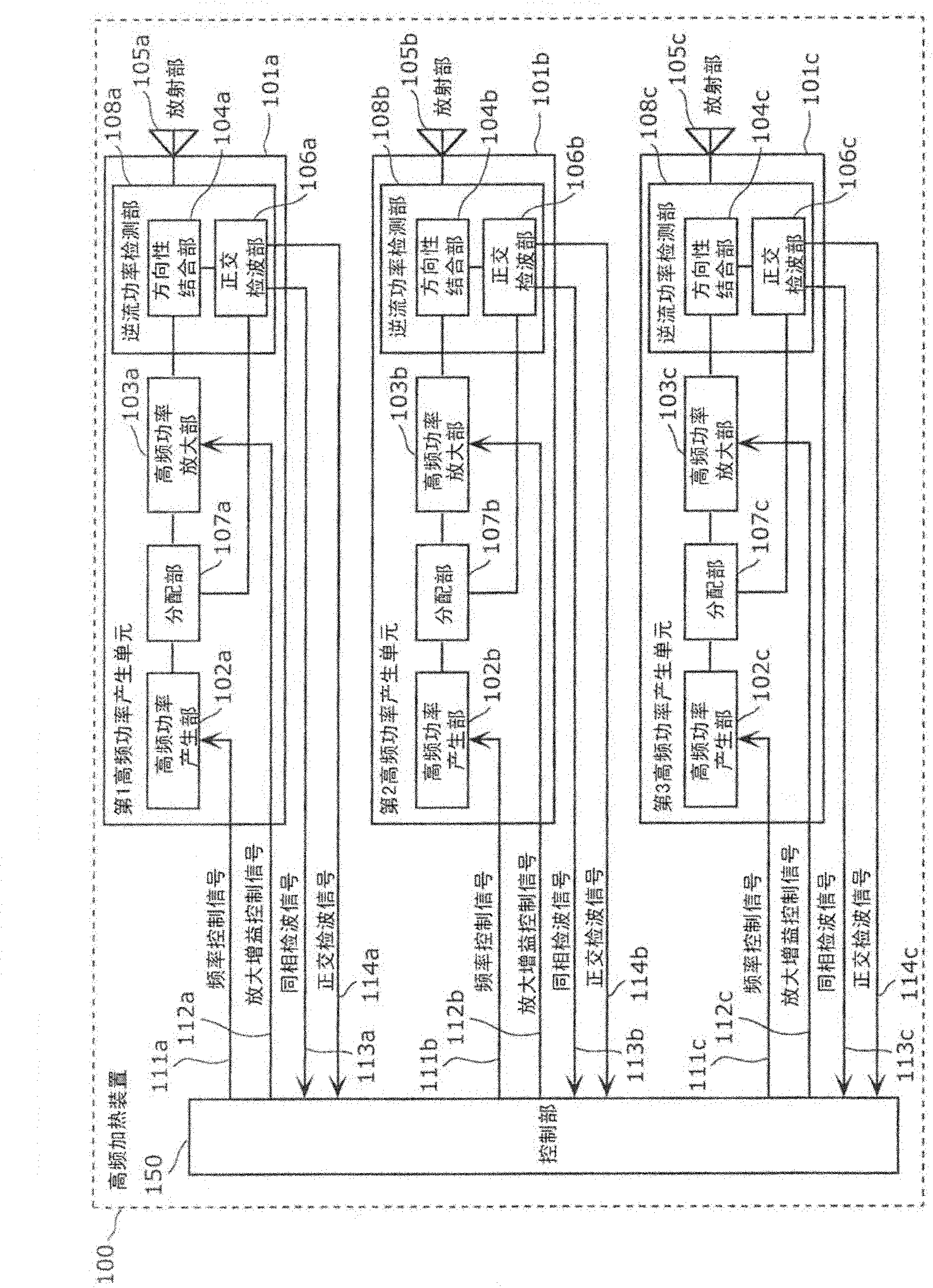
[0046] figure 1 It is a block diagram showing the configuration of the high-frequency heating device of the present invention.

[0047] The high-frequency heating device 100 has a first high-frequency power generation unit 101 a , a second high-frequency power generation unit 101 b , a third high-frequency power generation unit 101 c , and a control unit 150 . In addition, the first high-frequency power generation unit 101a, the second high-frequency power generation unit 101b, and the third high-frequency power generation unit 101c are sometimes described as the high-frequency power generation unit 101a, the high-frequency power generation unit 101b, and the high-frequency power generation unit 101b below. Power generating unit 101c. In addition, the high-frequency heating device 100 also has a heating chamber for accommodating an object to be heated.

[0048] The h...

no. 2 Embodiment approach

[0225] Next, a second embodiment of the present invention will be described with reference to the drawings.

[0226] This embodiment differs from the first embodiment in that each radio-frequency power generation unit has two radio-frequency power generation units instead of distribution units. According to such a configuration, the detection accuracy of the reverse flow power detected by the reverse flow power detection unit can be improved by appropriately setting the frequencies of the two high-frequency power generation units.

[0227] The following description will focus on differences from the first embodiment. In addition, in the description of this embodiment, the components having the same functions as those of the first embodiment are assigned the same reference numerals, and description thereof will be omitted. In addition, the description of the same operation as that of the first embodiment is also omitted.

[0228] Figure 11 It is a block diagram showing the ...


PUM


Abstract

Disclosed is a high-frequency heating device comprising: a plurality of high-frequency power generating units (101a, 101b, 101c), each of which generates high-frequency power; and a controller (150) that sets a combination of the different frequencies of the high-frequency power generated by the plurality of high-frequency power generating units (101a, 101b, 101c) for the plurality of high-frequency power generating units (101a, 101b, 101c). Back-flow power detection parts (108a, 108b, 108c) in the plurality of high-frequency power generating units (101a, 101b, 101c) individually detect the reflected power and the through power. Based on the phase and amplitude of the reflected power and through power that were detected, the control part (150) determines the combination of the different frequencies of the high-frequency power generated by the plurality of high-frequency power generating units (101a, 101b, 101c) when heating an object to be heated.

Description

technical field [0001] The present invention relates to a high-frequency heating device and a high-frequency heating method having a plurality of high-frequency power generating units having a high-frequency power generating unit composed of a semiconductor element. Background technique [0002] The high-frequency power generating unit of conventional high-frequency heating devices is generally composed of a vacuum tube called a magnetron. [0003] In recent years, the development of high-frequency heating devices using semiconductor elements such as gallium nitride (GaN) has been promoted to replace the magnetron. Such a high-frequency heating device can realize a compact and low-cost structure, and it is easy to control the frequency. Patent Document 1 discloses a technology for controlling the phase difference and frequency of high-frequency power radiated from a plurality of radiating parts to minimize backflow power and heat an object to be heated in an optimal state. ...

Claims


Application Information

Patent Timeline
Patent Type & Authority Applications(China)
IPC IPC(8): H05B6/68
CPCH05B6/705H05B2206/044H05B6/70H05B6/686Y02B40/143H05B6/72Y02B40/146Y02B40/00
Inventor 冈岛利幸石崎俊雄
Owner PANASONIC CORP
Why Eureka
Try Eureka