
Acetabular prosthesis of artificial hip joint with rotational ellipsoid joint interface

An acetabular prosthesis and ellipsoid technology, applied in the field of medical devices, can solve problems such as difficult to realize, increase the difficulty of acetabular prosthesis replacement, and unable to improve the interface mechanics and lubrication performance of spherical hip prosthesis

Active Publication Date: 2011-07-20
SHANGHAI NINTH PEOPLES HOSPITAL AFFILIATED TO SHANGHAI JIAO TONG UNIV SCHOOL OF MEDICINE
View PDF7 Cites 13 Cited by
  • Summary
  • Abstract
  • Description
  • Claims
  • Application Information

AI Technical Summary

Problems solved by technology

This technology has the following disadvantages: First, after the outer cup of the acetabular prosthesis is designed to be elliptical, due to the certain ratio requirements and spatial orientation requirements between the long and short axes of the elliptical outer cup, the doctor cannot The acetabular fossa must be manually reamed into an elliptical surface to match the outer cup of the elliptical acetabular prosthesis, which will undoubtedly greatly increase the difficulty of acetabular prosthesis replacement. Difficult to achieve
Therefore, the elliptical acetabular prosthesis described in this technology will not be able to improve the mechanical and lubricative properties of the joint interface of spherical hip prosthesis

Method used


Image

  • Acetabular prosthesis of artificial hip joint with rotational ellipsoid joint interface
  • Acetabular prosthesis of artificial hip joint with rotational ellipsoid joint interface
  • Acetabular prosthesis of artificial hip joint with rotational ellipsoid joint interface

Examples


Embodiment

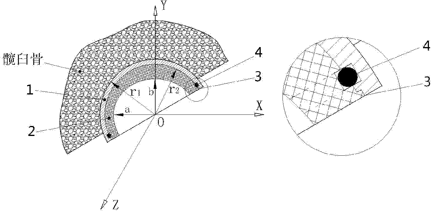
[0027] According to the patient's CT images, an artificial hip acetabular prosthesis with a rotational ellipsoidal joint interface was designed to replace the left acetabulum of the patient's hip.

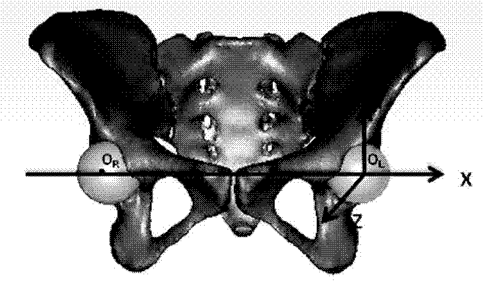
[0028] Such as figure 1 As shown, the first step is to reconstruct the three-dimensional anatomical model of the hip joint according to the CT images of the patient's hip joint, and use the spherical surface to fit the three-dimensional surface of the bony acetabular fossa on both sides. The center of the sphere is set as the origin of the measurement coordinate system of the acetabular prosthesis, and the line connecting the center of the sphere on both sides of the fitted sphere is the X-axis.

[0029] The three-dimensional anatomical shape model includes: the three-dimensional curved surface shape of the bony acetabular socket.

[0030] The second step is to set the plane where the coronal plane of the hip joint is located as the XY plane, the line passing through the origin of...


PUM

PropertyMeasurementUnit
Thicknessaaaaaaaaaa

Abstract

The invention belongs to the technical field of medical devices and discloses an acetabular prosthesis of an artificial hip joint with a rotational ellipsoid joint interface, which comprises an acetabular outer cup made of a cobalt / chrome / molybdenum alloy and an acetabular liner made of polyethylene. The liner of the acetabular prosthesis comprises a spherical outer surface and a rotational ellipsoid inner surface, wherein the radius of the spherical outer surface, i.e. the outside diameter of the liner, is equal to the subtraction of the thickness of the acetabular outer cup from the radius of the acetabular prosthesis outer cup; the length of the major axis of the rotational ellipsoid inner surface is equal to the subtraction of the thickness of the liner from the outside diameter of the liner; and the length of the minor axis of the rotational ellipsoid inner surface is equal to the multiplication of the length of the major axis by 0.98. A positioning groove and a clamping ring arearranged between the liner and the outer cup to achieve the effect of fixation. According to the shapes of acetabular fossa of different patients, the acetabular prostheses of different specifications are designed and manufactured so as to solve the problem of stress concentration on the joint interface of the spherical artificial hip joint in the prior art and meet the needs for individual treatment of different patients. Therefore, the acetabular prosthesis provided by the invention is truly put into effect in clinics.

Description

technical field [0001] The invention relates to a device in the technical field of medical instruments, in particular to an artificial hip acetabular prosthesis with a rotational ellipsoidal joint interface. Background technique [0002] The artificial hip joint is currently one of the most effective medical implants for clinically reconstructing the function of the damaged hip joint. It has been widely used in clinical practice, and more than 1 million patients worldwide receive artificial hip joint replacement every year. However, artificial hip joints still have the problem of postoperative aseptic loosening of the joint prosthesis due to the wear of the joint interface of the prosthesis, which affects the treatment effect. Studies have shown that the shape optimization of the hip prosthesis in the design of the head and socket joint interface will significantly affect the mechanical properties and lubrication performance of the prosthesis joint interface, slow down the w...

Claims


Application Information

Patent Timeline
IPC IPC(8): A61F2/34A61L27/06A61L27/18
CPCA61F2/34A61F2002/30001
Inventor 顾冬云
Owner SHANGHAI NINTH PEOPLES HOSPITAL AFFILIATED TO SHANGHAI JIAO TONG UNIV SCHOOL OF MEDICINE
Learn More