

Selective laser sintered single-face powder supplying device realized by adopting powder returning groove
A powder feeding device, laser sintering technology, applied in laser welding equipment, process efficiency improvement, manufacturing tools and other directions, to achieve the effect of reducing the overall size, improving the reliability of the equipment, and reducing the complexity of the equipment
- Summary
- Abstract
- Description
- Claims
- Application Information
AI Technical Summary
Problems solved by technology
Method used
Image

Examples
Embodiment 1
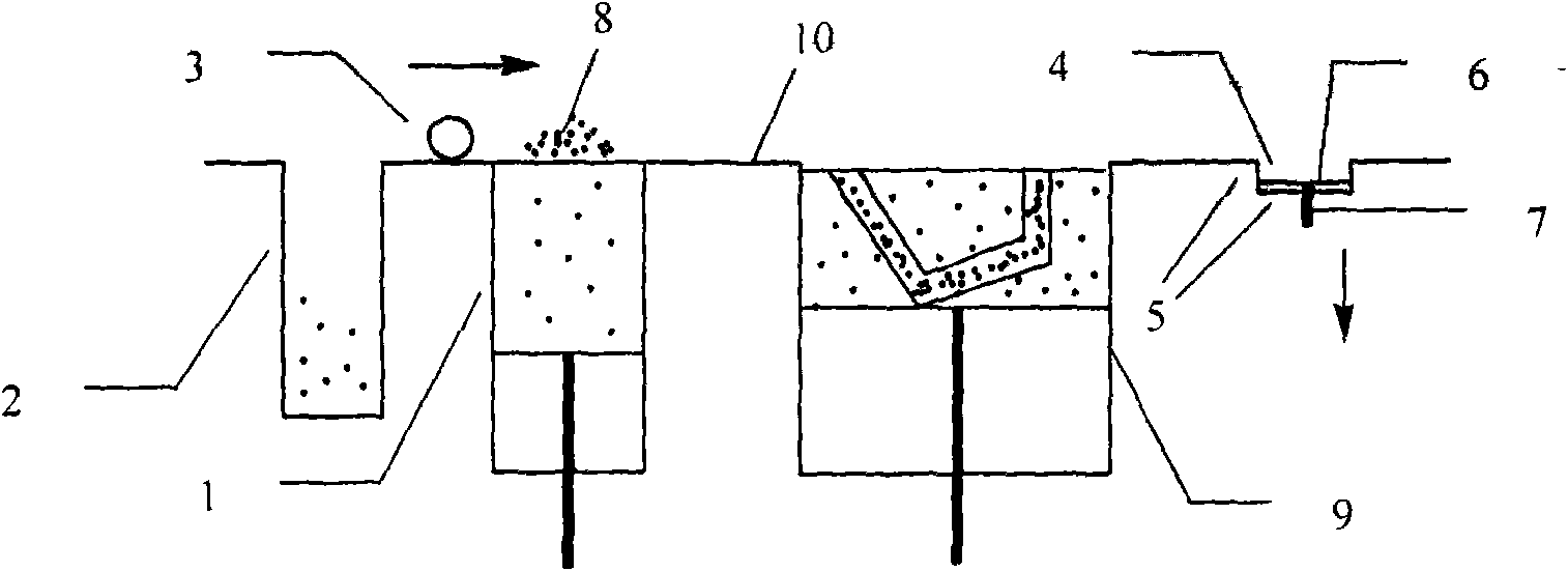
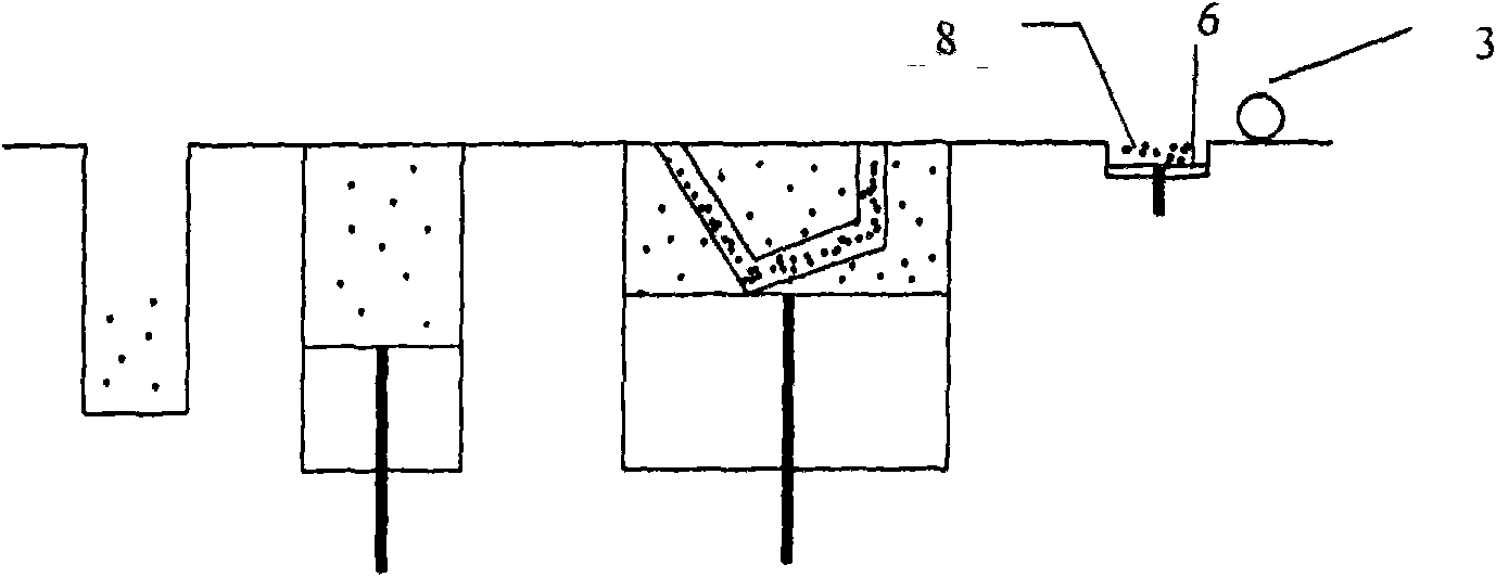
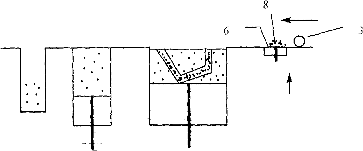
[0013] Such as Figure 1A As shown in -D, 1 is the powder feeding cylinder below, 2 is the powder overflow cylinder, 3 is the powder spreading roller, 4 is the powder returning tank, and the powder returning tank 4 includes the cylinder body 5, the movable bottom plate 6 and the control connected with the movable bottom plate The shaft 7, the powder feeding cylinder 1 and the powder overflow cylinder 2 are located on the left side of the working cylinder 9, and the powder return tank 4 is located on the right side of the working cylinder 9. Such as Figure 1A As shown, the powder feeding cylinder 6 first supplies the quantitative powder material 8 of the working platform 10, and the amount of the powder material supplied is slightly greater than the amount of powder required for two powder spreading, and the powder spreading roller starts from the left and goes right to spread the powder. At the same time, the control shaft 7 controls the movable bottom plate 6 of the powder re...
Embodiment 2
[0015] Such as Figure 2A As shown in -D, 1' is the upper feeding powder cylinder, 2 is the powder overflow cylinder, 3 is the powder spreading roller, 4 is the powder return tank, and the powder return tank 4 includes the cylinder body 5, the movable bottom plate 6 and the movable bottom plate The control shaft 7, the powder feeding cylinder 1 and the powder overflow cylinder 2 are located on the left side of the working cylinder 9, and the powder return tank 4 is located on the right side of the working cylinder 9. Such as Figure 2A As shown, the powder feeding cylinder 6 first supplies the quantitative powder material 8 of the working platform 10, and the amount of the powder material supplied is slightly greater than the amount of powder required for two powder spreading, and the powder spreading roller starts from the left and goes right to spread the powder. At the same time, the control shaft 7 controls the lower position of the movable bottom plate 6 of the powder re...
PUM
 Abstract
Description
Claims
Application Information