Printing press with cylinder adjustment and cylinder conversion device

A conversion device and printing machine technology, applied to rotary printing machines, printing machines, printing, etc., can solve the problem that the pressure of the rolling pillow cannot be kept constant

Active Publication Date: 2015-03-11
HEIDELBERGER DRUCKMASCHINEN AG
View PDF7 Cites 0 Cited by
  • Summary
  • Abstract
  • Description
  • Claims
  • Application Information

AI Technical Summary

Problems solved by technology

The disadvantage of having a compression spring is that it cannot keep the roller pillow pressure constant enough

Method used


Image

  • Printing press with cylinder adjustment and cylinder conversion device
  • Printing press with cylinder adjustment and cylinder conversion device

Examples


Embodiment Construction

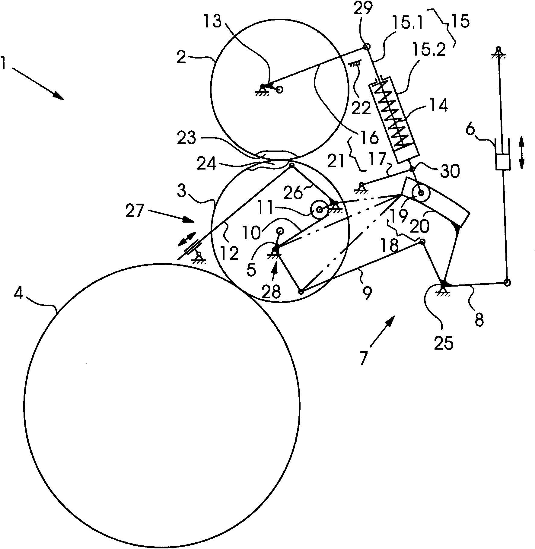
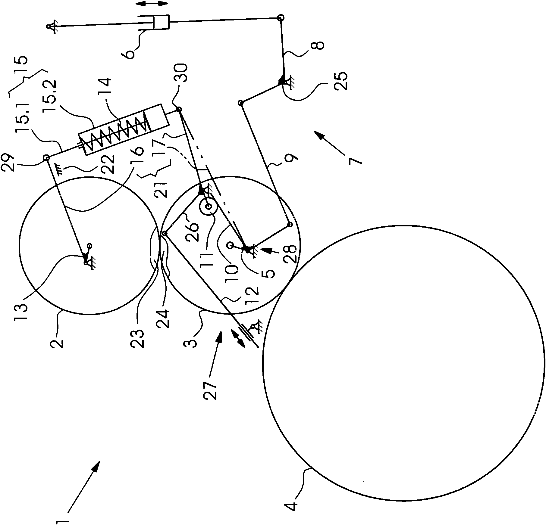
[0014] exist figure 1 and 2 In , members and elements corresponding to each other are provided with the same reference numerals.

[0015] exist figure 1 A printing press 1 for lithographic offset printing on printing sheets is shown in FIG. The printing press 1 comprises a plate cylinder 2 , a blanket cylinder 3 and an impression cylinder 4 . The blanket cylinder 3 is mounted in a first eccentric bearing 5 , by adjusting the eccentric bearing, the blanket cylinder 3 can optionally be adjusted into an initial printing position and an end printing position. The first eccentric bearing 5 is an integral part of a switching device 28 for switching the blanket cylinder 3 relative to the impression cylinder 4 at the start of printing and at the end of printing. The adjustment of the eccentric bearing 5 is driven by a pneumatic cylinder 6 via a four-joint transmission 7 .

[0016] The four-hinge transmission device 7 includes a double-arm driving rocker 8 , a connecting rod 9 and...


PUM


Abstract

A printing press includes a printing form cylinder, a blanket cylinder, an impression cylinder, an adjusting device for setting a printing pressure between the blanket cylinder and the impression cylinder, a control device for throwing the pressure of the blanket cylinder on and off relative to the impression cylinder and springs for producing bearer ring pressure between bearer rings of the printing form cylinder and bearer rings of the blanket cylinder. The springs are integrated into coupling links and are connected to at least one of the two devices in such a way that, as a result of the actuation of that device, the springs are also adjusted, in order to keep the bearer ring pressure at least substantially constant.

Description

technical field [0001] The invention relates to a printing press comprising a plate cylinder, a blanket cylinder, an impression cylinder, an adjustment device for adjusting the printing feed between said blanket cylinder and said impression cylinder, The conversion device for the printing press and the printing release pressure of the blanket cylinder relative to the impression cylinder is used to generate the pillow pressure between the pillow of the printing plate cylinder and the pillow of the blanket cylinder spring. Background technique [0002] A printing press with a tracking system is described in DE 10 2007 009 884 A1. The tracking system comprises two actuating drives which are connected via so-called spring legs to eccentric bearings in which the plate cylinder is mounted. The two actuating drives are control-coupled via an electronic control unit to a further actuating drive. The further adjusting drive is part of an adjusting device for adjusting the printing...

Claims


Application Information

Patent Timeline
Patent Type & Authority Patents(China)
IPC IPC(8): B41F13/34
CPCB41F13/21B41F13/34
Inventor R·金德根S·库尔茨尔
Owner HEIDELBERGER DRUCKMASCHINEN AG
Why Eureka
Try Eureka