Self-liquid-supply pneumatic hydraulic pump having liquid return function

A pneumatic hydraulic pump and function technology, applied in the field of hydraulic pumps, can solve the problems of inconvenient operation and use, large space occupation, restricted use, etc., and achieve the effect of effectively using space, smooth liquid supply, and avoiding damping.

Inactive Publication Date: 2015-08-05
大大科技(宁国)有限公司
View PDF0 Cites 6 Cited by
  • Summary
  • Abstract
  • Description
  • Claims
  • Application Information

AI Technical Summary

Problems solved by technology

However, the hydraulic pump and the hydraulic oil storage box currently on the market are two independent systems. Each time you use it, you need to carry the hydraulic pump and the hydraulic oil storage box at the same time to provide power for the hydraulic cylinder, but carry the hydraulic pump and the hydraulic oil storage box at the same time. The box is extremely inconvenient and easy to lose. It is necessary to connect the hydraulic pump and the hydraulic oil storage box with oil pipes during use. The operation is complicated and takes up a lot of space. The use of the oil box; at present, when the hydraulic cylinder is unloaded, it is necessary to connect the hydraulic cylinder to the hydraulic oil storage box, so that the oil in the hydraulic cylinder can flow back to the oil storage box, which is inconvenient to operate and use

Method used


Image

  • Self-liquid-supply pneumatic hydraulic pump having liquid return function
  • Self-liquid-supply pneumatic hydraulic pump having liquid return function
  • Self-liquid-supply pneumatic hydraulic pump having liquid return function

Examples


Embodiment Construction

[0015] In order to make the technical means, creative features, goals and effects achieved by the present invention easy to understand, the present invention will be further described below in conjunction with specific illustrations.

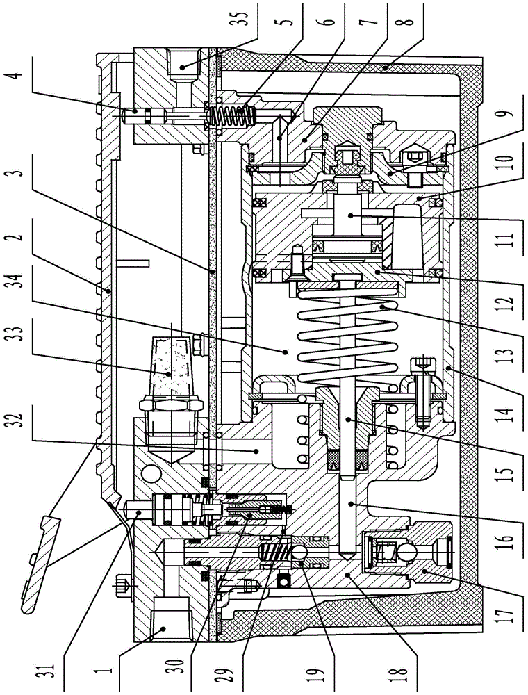
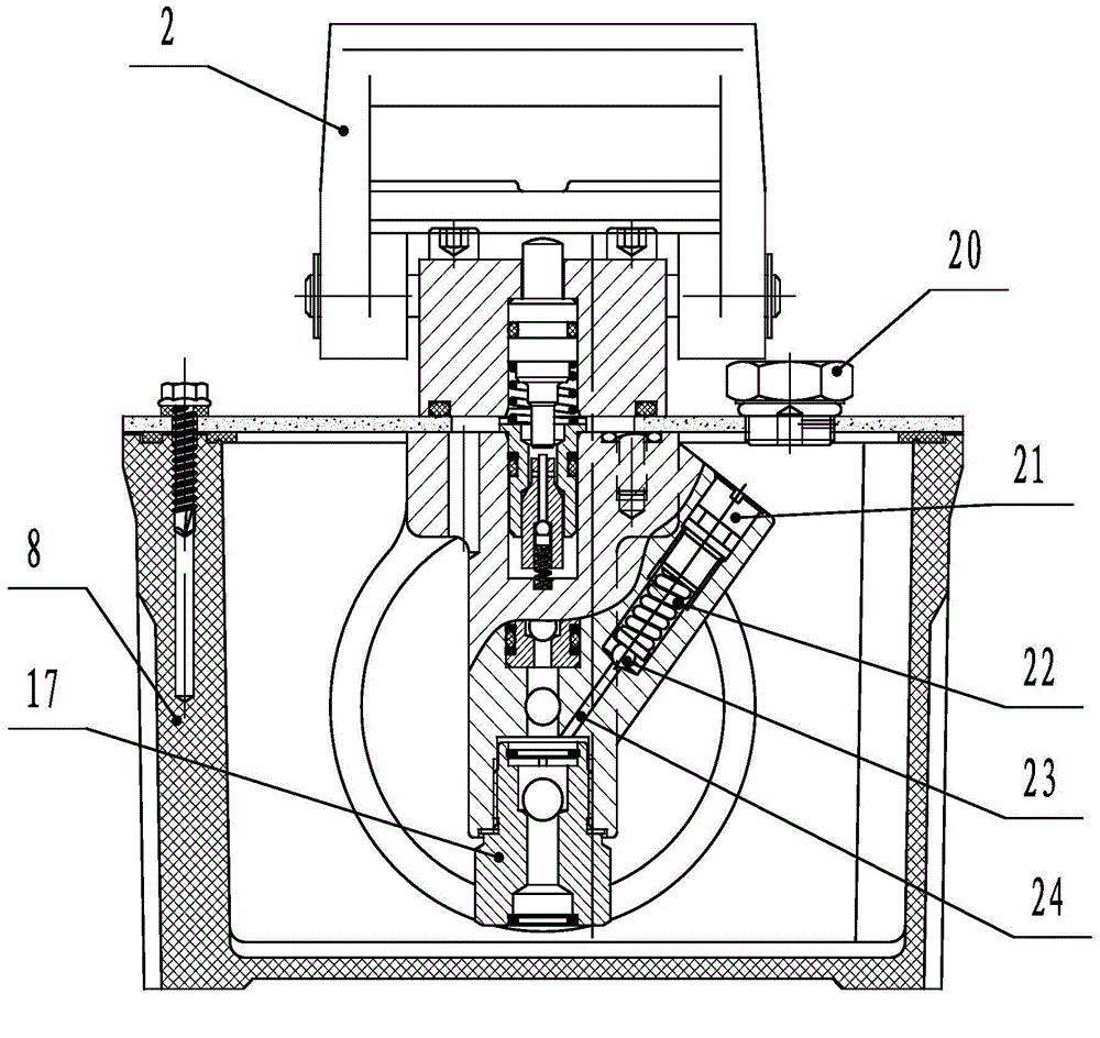
[0016] Such as figure 1 , 2 As shown, a self-supply liquid pneumatic hydraulic pump with liquid return function mainly includes pedal 2, intake control thimble 4, oil storage box 8, air pressure body 7, air piston 10, extrusion piston rod 15, oil pressure Body 18, oil suction check valve 17, oil outlet check valve 19 and oil outlet, characterized in that: the air pressure body 7, air piston 10, extrusion piston rod 15, oil pressure body 18 and oil outlet check valve 19 is located in the oil storage box 8, the top of the oil storage box 8 is sealed by fixing the partition 3 with bolts, the pedal 2 is fixed on the right side of the partition 3 by a hinge, and the inside of the air pressure body 7 The air intake control thimble 4 is connected thr...


PUM


Abstract

The invention relates to a self-liquid-supply pneumatic hydraulic pump having a liquid return function. A pneumatic body, a gas piston, an extrusion piston rod, an oil pressure body and an oil outlet one-way valve are positioned in an oil storage box; a pedal is fixed at the right side of a separation plate through a hinge; a high-pressure oil through hole is formed in the oil pressure body, and is connected with the internal of a cylinder and an oil outlet; the oil outlet one-way valve and an oil absorbing one-way valve are mounted in the middle of the high-pressure oil through hole; an oil return through hole is formed in the right end of the upper side of the oil outlet one-way valve, and is connected with an oil outlet hole and the internal of the oil storage box; an oil return valve is arranged in the middle position of the oil return through hole; and an oil return control thimble is arranged above the oil return valve, and is positioned at the left side of the pedal. The pump uses the technical breakthrough for integrating functions of the hydraulic pump and the hydraulic oil storage box to prevent such complex procedures as connection between a traditional hydraulic cylinder power source hydraulic pump and the hydraulic oil storage box and to synchronously realize the liquid supply and liquid return functions of the hydraulic cylinder.

Description

technical field [0001] The invention relates to the technical field of hydraulic pumps, in particular to a self-supply liquid pneumatic hydraulic pump with liquid return function. Background technique [0002] The hydraulic pump is an intermediate necessary power system connecting the hydraulic oil storage box and the hydraulic cylinder. The hydraulic pump injects the hydraulic oil in the hydraulic oil storage box into the hydraulic cylinder through the hydraulic pump to realize the lift process of the hydraulic cylinder. However, the hydraulic pump and the hydraulic oil storage box currently on the market are two independent systems. Each use needs to carry the hydraulic pump and the hydraulic oil storage box at the same time to provide power for the hydraulic cylinder, but carry the hydraulic pump and the hydraulic oil storage box at the same time. The box is extremely inconvenient and easy to lose. During use, the hydraulic pump and the hydraulic oil storage box need to b...

Claims


Application Information

Patent Timeline
Patent Type & Authority Applications(China)
IPC IPC(8): F04B23/02F04B9/14F04B53/10F04B53/16
Inventor 唐坤瑞钱昌雲
Owner 大大科技(宁国)有限公司
Why Eureka
Try Eureka