Combined type pump house of drainage pump station

A drainage pumping station and combined technology, which is applied in the field of building water supply and drainage, can solve the problems of large building space drainage pumping station, large groundwater buoyancy, drainage pumping station occupancy, etc., so as to save space and floor area, reduce cost, reduce The effect of footprint

Inactive Publication Date: 2011-07-20
TUS DESIGN GRP CO LTD
View PDF7 Cites 9 Cited by
  • Summary
  • Abstract
  • Description
  • Claims
  • Application Information

AI Technical Summary

Problems solved by technology

[0006] The purpose of the present invention is to provide a combined drainage pumping station pump room, which solves the problems in the prior art that the dra

Method used


Image

  • Combined type pump house of drainage pump station
  • Combined type pump house of drainage pump station
  • Combined type pump house of drainage pump station

Examples


Embodiment

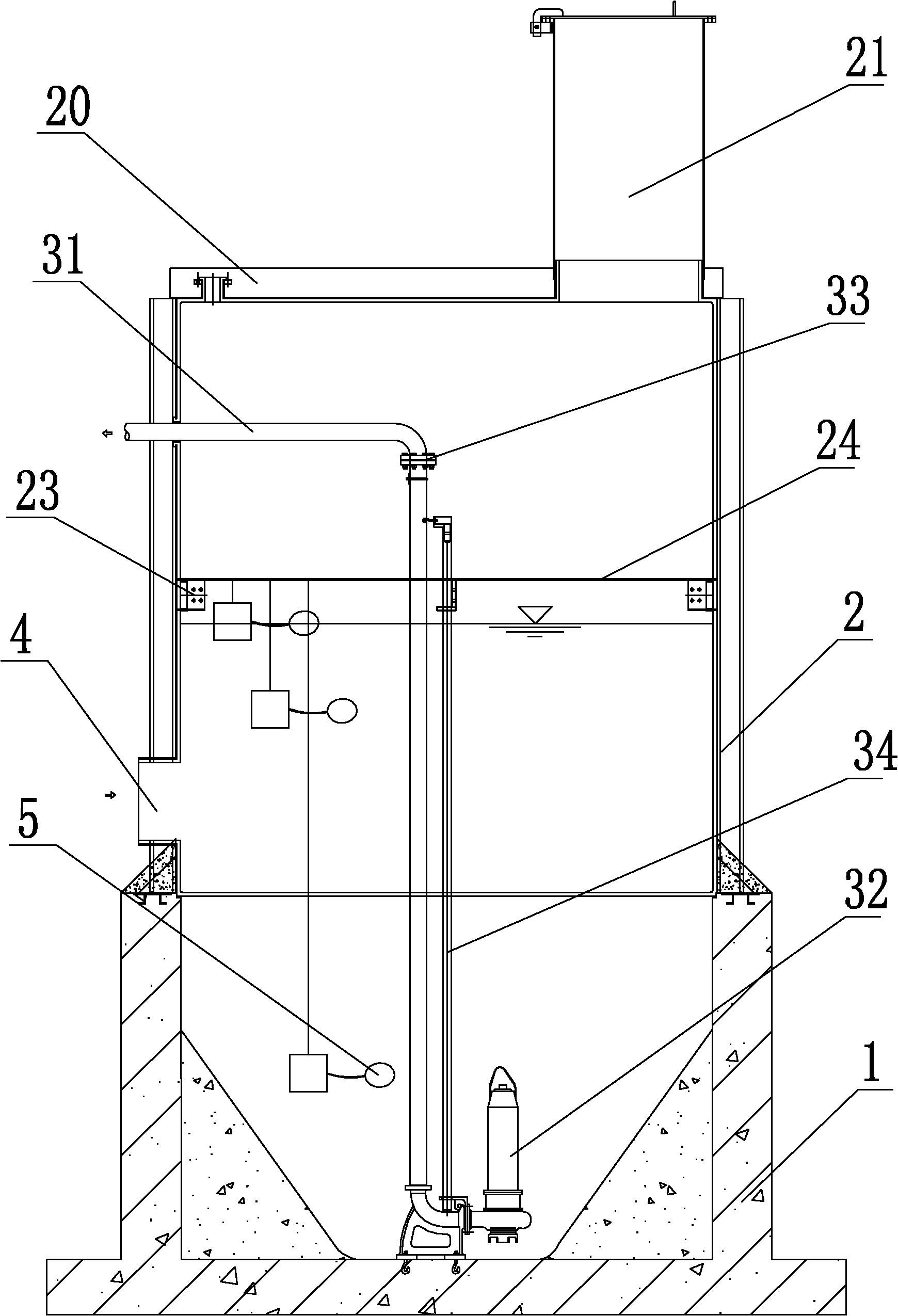
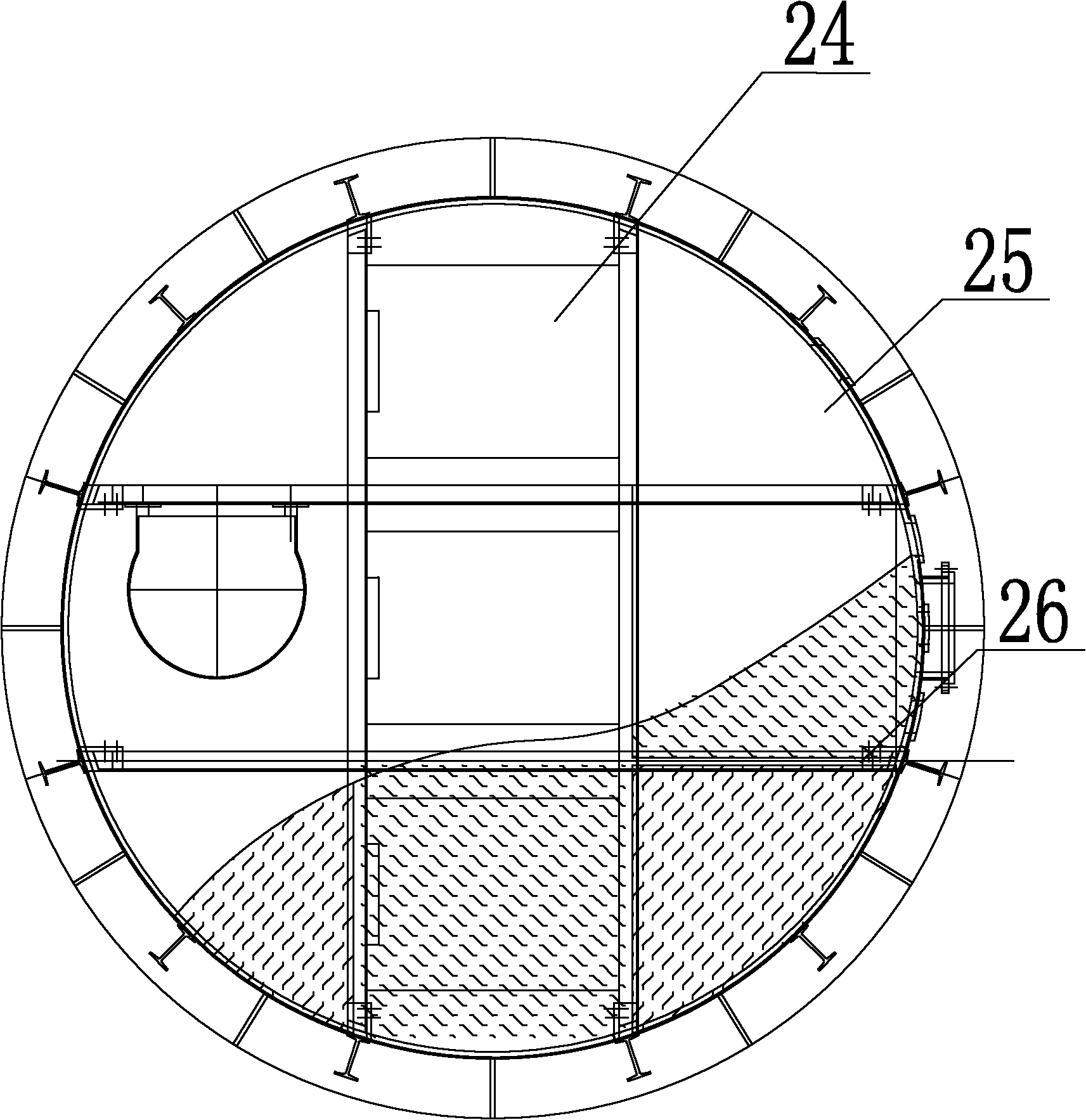
[0032] Such as Figure 1 ~ Figure 3 As shown, the pump room of the combined drainage pumping station includes a base 1, a cylinder 2 is erected on the base 1, a water pump 3 is arranged in the cylinder, the water inlet of the water pump is at the lowest position in the base 1, and the water pump The water outlet is set on the cylinder wall.

[0033] The base 1 is a reinforced concrete container, the upper end of the reinforced concrete container is open, and the lower end of the water pump 3 is fixed to the bottom surface of the reinforced concrete container. The reinforced concrete container is a container with a funnel-shaped inner wall. The upper end of the cylinder top cover compacts the soil (6)

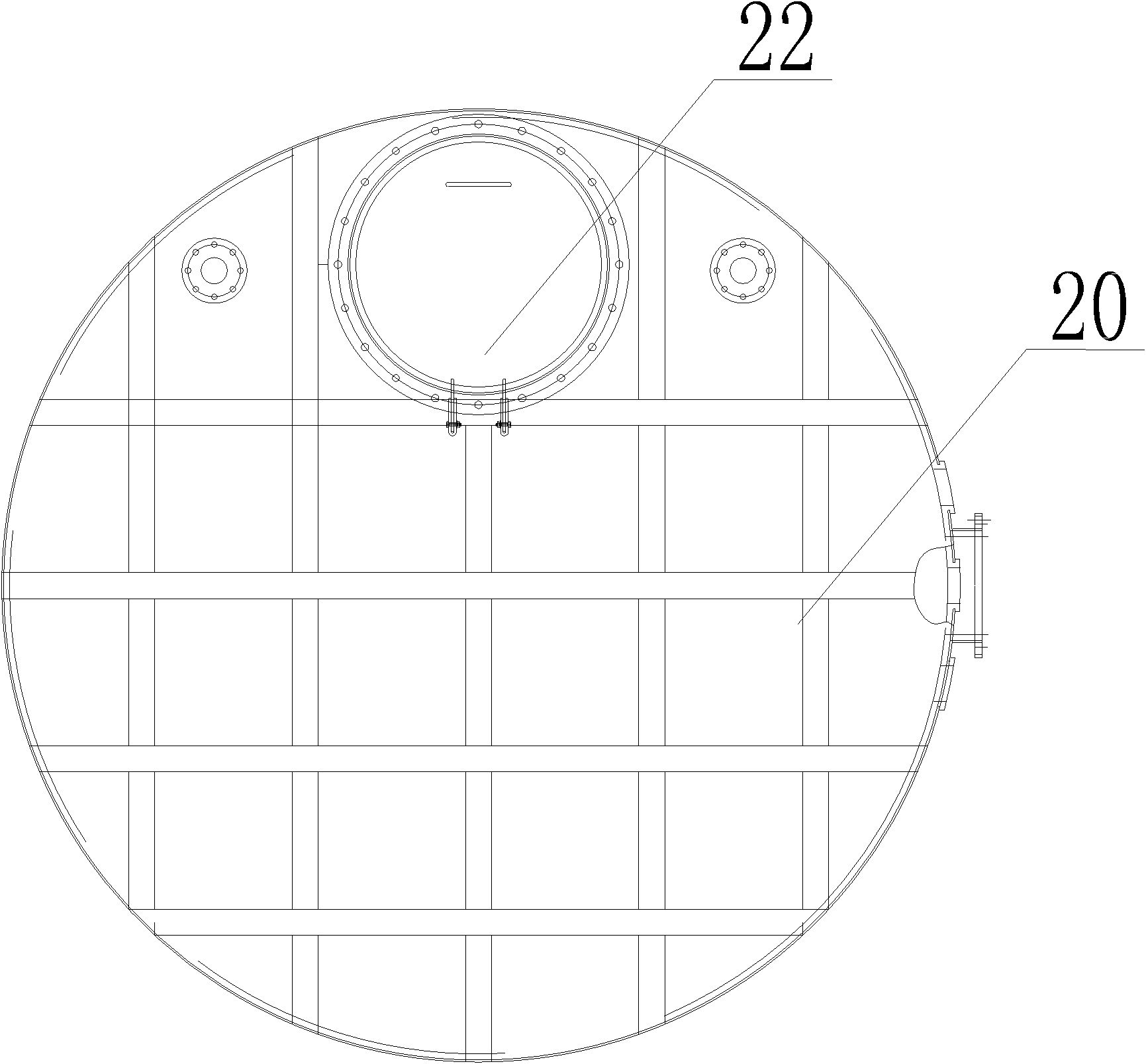
[0034] The lower end of the cylinder is sealed and fixed with the base, and the upper end is provided with a top cover 20, on which an inspection cylinder 21 for maintenance is welded and fixed, and the inspection cylinder 21 is provided with an inspection cover 22, and one en...


PUM


Abstract

The invention discloses a combined type pump house of a drainage pump station, which comprises a base (1), and is characterized in that the base (1) is erected with a cylinder body (2); the cylinder body is internally provided with a water pump (3); a water inlet of the water pump is arranged at the lowest position in the base (1); and a water outlet of the water pump is positioned on the wall of the cylinder body. By using the pump house, the problems that the drainage pump station is larger in occupied building space or can not be used when being born higher buoyancy force of underground water and the like can be solved.

Description

technical field [0001] The invention belongs to the technical field of building water supply and drainage, and in particular relates to a combined drainage pumping station. Background technique [0002] Drainage pumping stations are pumping stations used to remove flood water and reduce groundwater levels. When the waste water needs to be lifted in the middle and the end of the drainage pipeline, pumping stations are set up, which are called midway pumping stations and terminal pumping stations. When the surrounding environment of the drainage pumping station has special requirements, the midway pumping station is sometimes hidden underground. The main components of the drainage pumping station are the pump room and the sump, and the pump room is equipped with a unit composed of water pumps and power equipment. Power equipment is usually an electric motor with a switchboard. Lifting equipment is provided on the top of the pump room for lifting the unit during installation...

Claims


Application Information

Patent Timeline
IPC IPC(8): E04H5/02E03F5/22
Inventor 王春明顾莹
Owner TUS DESIGN GRP CO LTD
Why Eureka
Try Eureka