Two-surface friction stir welding method and device, and tool set for two-surface friction stir welding

A friction stirring and joining method technology, applied in manufacturing tools, welding equipment, metal processing equipment, etc., can solve problems such as difficulty in applying surface pressure, deterioration of joint quality, poor joint, etc., to reduce operating costs, increase softening area, Effect of preventing heat loss

Active Publication Date: 2011-07-20
PRIMETALS TECHNOLOGIES JAPAN LTD
View PDF6 Cites 11 Cited by
  • Summary
  • Abstract
  • Description
  • Claims
  • Application Information

AI Technical Summary

Problems solved by technology

[0016] In addition, even if these tool materials are used, the tool life is shortened due to thermal shock, tool wear, and bending stress acting on the probe, which hinders the popularization of friction stir welding for materials with a high melting point exceeding 1000°C. main reason
[0017] The second is the problem of bad joints
Due to the fluctuation of the surface pressure, the heat of friction fluctuates, and there is a problem that the quality of the joint part deteriorates.
[0021] Furthermore, in Patent Document 1 figure 2 In the double-shaft shoulder described in a, since the vertical axes of the shoulders of the rotary tool disposed opposite to each other are the same, the axis of the rotary tool cannot be inclined, and it is difficult to apply the desired surface pressure required for stirring.
If the desired surface pressure required for stirring cannot be applied, the fluidity of the joint portion decreases, causing joint defects.
[0022] The third is the problem of the fracture of the metal plate caused by friction

Method used


Image

  • Two-surface friction stir welding method and device, and tool set for two-surface friction stir welding
  • Two-surface friction stir welding method and device, and tool set for two-surface friction stir welding
  • Two-surface friction stir welding method and device, and tool set for two-surface friction stir welding

Examples


Embodiment Construction

[0141] Embodiments of the present invention will be described below with reference to the drawings.

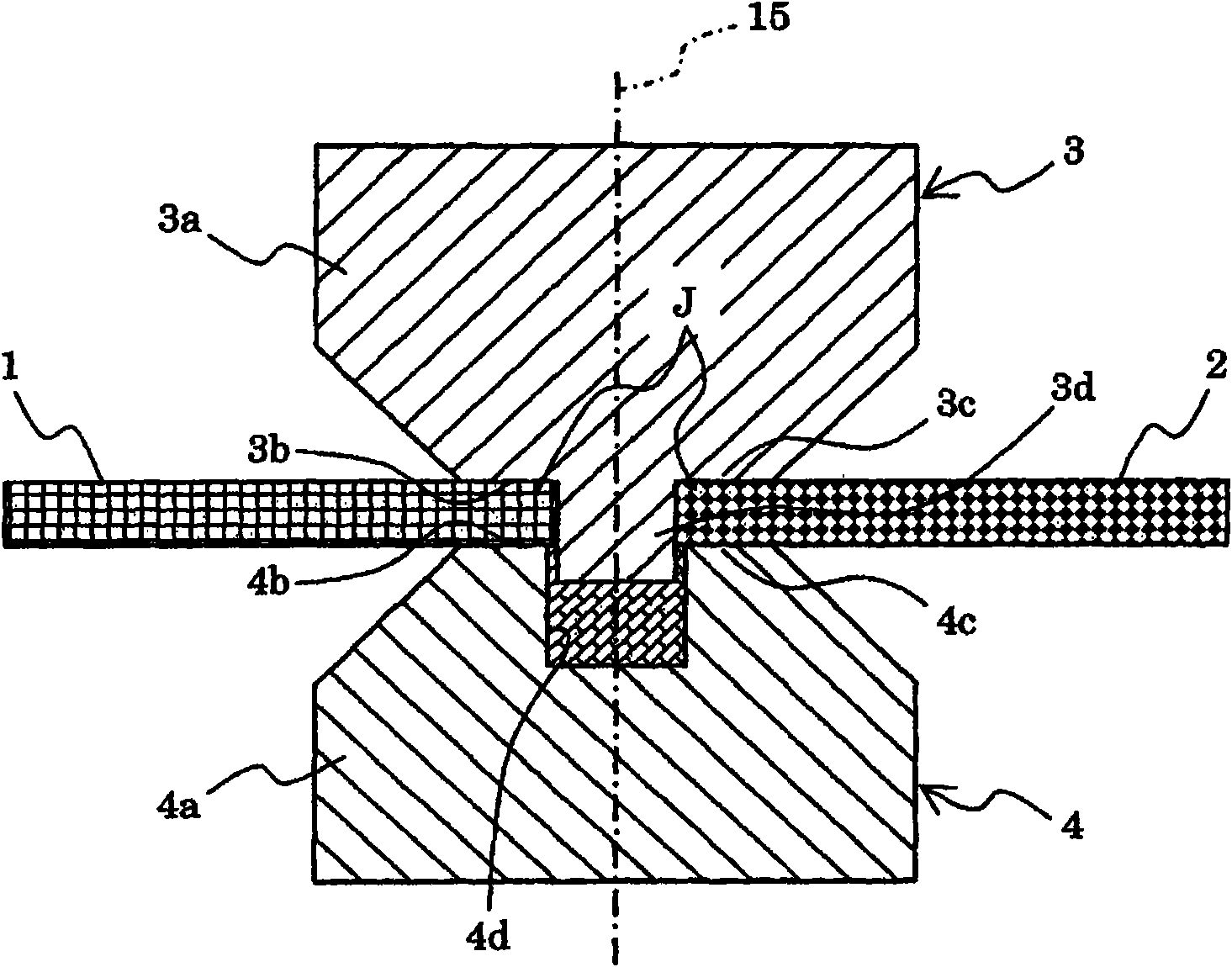
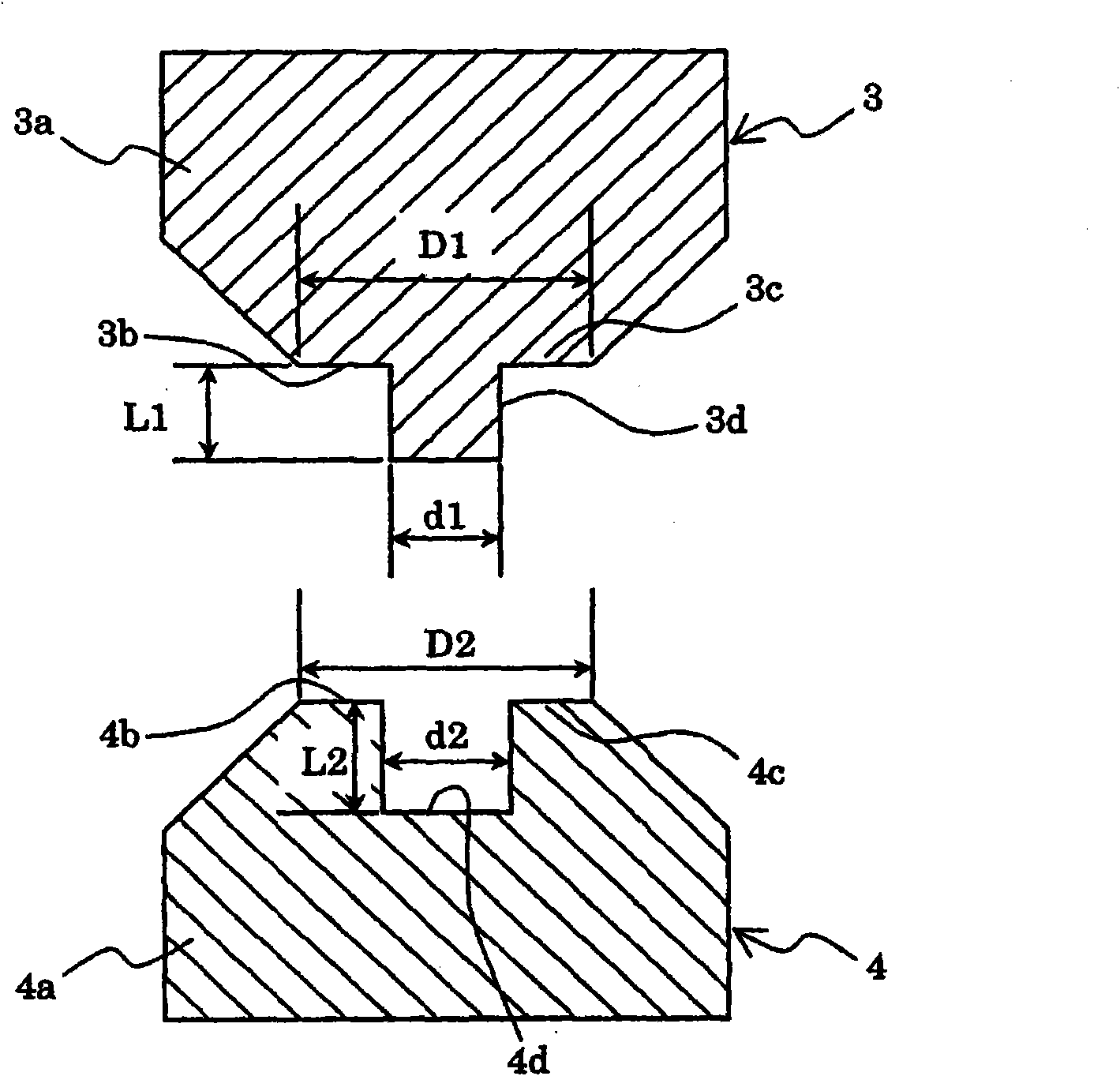
[0142] figure 1 and figure 2 It is an enlarged cross-sectional view of a tool tip portion of a tool set for double-sided friction stir welding according to an embodiment of the present invention, figure 1 Indicates the state of use of the tool set at the time of engagement, figure 2 Indicates the dimensional relationship of each part. The form of joining is, for example, butt welding. In addition, in this specification, a joint part means the part which should join two metal plates, and corresponds to a butt joint part in butt welding, and corresponds to an overlapping part in lap welding.

[0143] exist figure 1 and figure 2In this embodiment, the tool set for double-sided friction stir welding has first and second rotary tools 3 and 4, and the first and second rotary tools 3 and 4 are arranged facing each other at the joint of two metal plates 1 and 2. The surfa...


PUM

PropertyMeasurementUnit
melting pointaaaaaaaaaa
thicknessaaaaaaaaaa

Abstract

The present invention provides a two-surface friction stir welding method and device, and a tool set for two-surface friction stir welding. In order to economically perform two-surface friction stir welding resulting in high joint strength, a first and second rotation tool (3, 4) each has a tool body (3a, 4a) forming a shoulder section (3c, 4c) on the tip portion. The first rotation tool (3) further has a protrusion (3d) formed so as to protrude from the tip portion of the tool body, and the second rotation tool (4) further has a concavity (4d) which is formed in the tip portion of the tool body and which accommodates the tip of the protrusion (3d) during welding of two metal plates (1, 2). The first and second rotation tools are positioned oppositely on the front and back faces of the joining area (J) of the metal plates, and are moved towards each other. The tip of the protrusion of the first rotation tool is inserted into the concavity of the second rotation tool, the shoulder surfaces (3b, 4b) of the shoulder sections of the first and second rotation tool are pressed onto the front and back sides of the joining area, and in that state, the first and second rotation tools are moved along the joining area, friction stirring the entire joining area in the thickness direction of the plates with the first and the second rotation tools.

Description

technical field [0001] The present invention relates to a double-sided friction stir welding method and device for friction stirring and joining a joint of metal materials from both sides, and a tool set for double-sided friction stir welding. Background technique [0002] There is known a friction stir welding technique in which the surface of a shoulder portion provided on a tool body of the rotary tool is brought into contact with the surface of a joint member while rotating the rotary tool, and the friction between the surface of the shoulder portion and the joint member is utilized. The frictional heat on the surface performs friction stirring, and the materials to be joined are stirred and joined in a solid state below the melting point. This joining technology mainly uses aluminum alloys and is being put into practical use in various industrial fields. [0003] The conventional friction stir welding technology is roughly divided into one-sided friction stir welding a...

Claims


Application Information

Patent Timeline
Patent Type & Authority Applications(China)
IPC IPC(8): B23K20/12B23K20/26
CPCB23K20/1245B23K20/1255B23K20/126
Inventor 加贺慎一小野濑满富永宪明斋藤武彦芳村泰嗣平野聪朴胜焕
Owner PRIMETALS TECHNOLOGIES JAPAN LTD
Why Eureka
Try Eureka