Brake

A technology of brakes and brake discs, applied in the direction of brake type, axial brake, brake actuator, etc., can solve the problem of strong fluctuation of braking force, and achieve the effect of good adjustability

Active Publication Date: 2013-10-16
ZF CV SYST EURO BV
View PDF8 Cites 0 Cited by
  • Summary
  • Abstract
  • Description
  • Claims
  • Application Information

AI Technical Summary

Problems solved by technology

This cycle occurs repeatedly and results in strong fluctuations in braking force

Method used


Image

  • Brake
  • Brake
  • Brake

Examples


Embodiment Construction

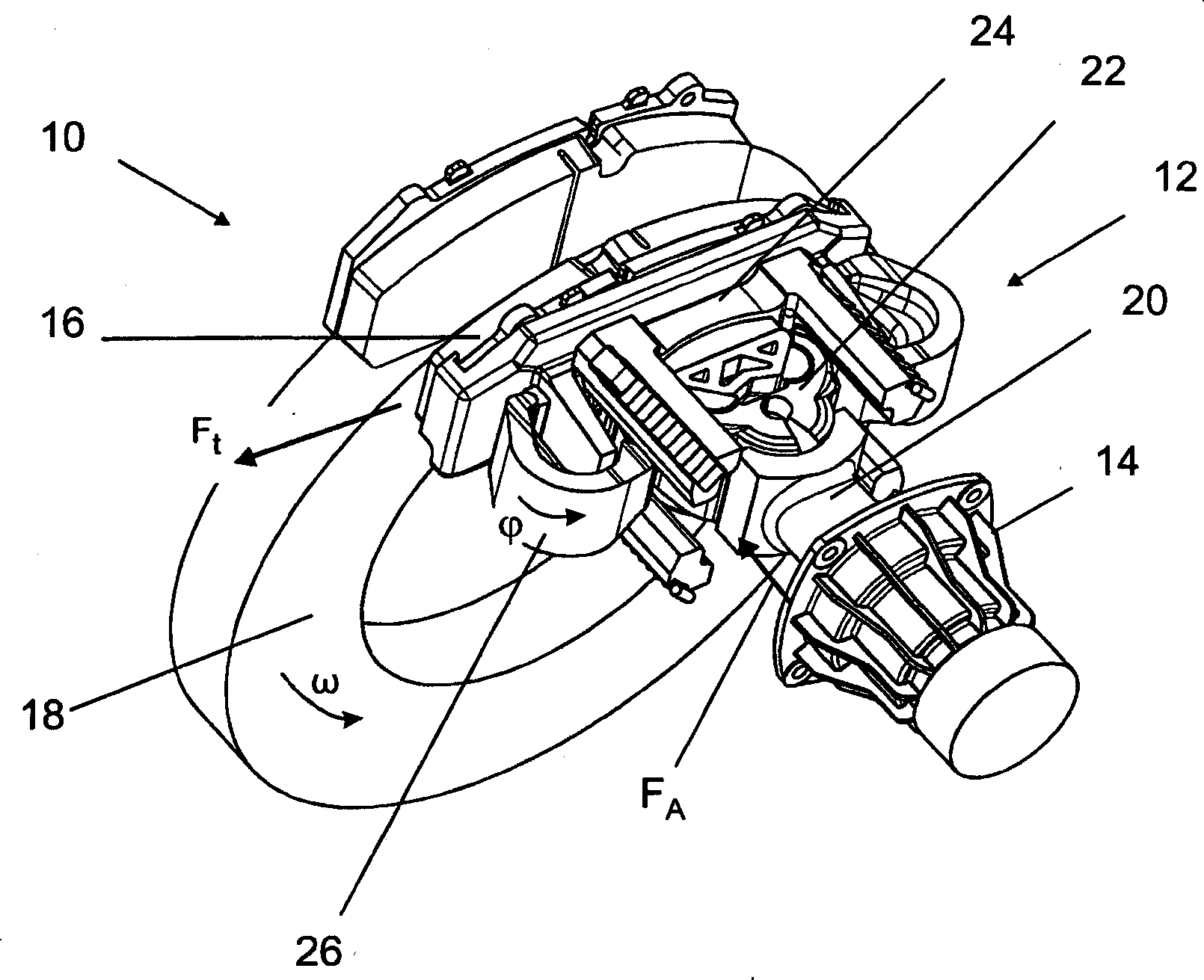
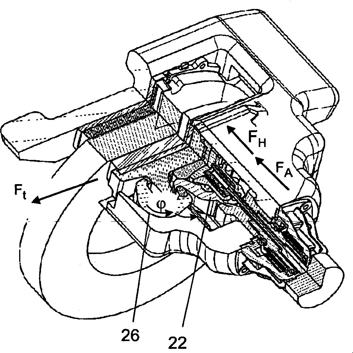
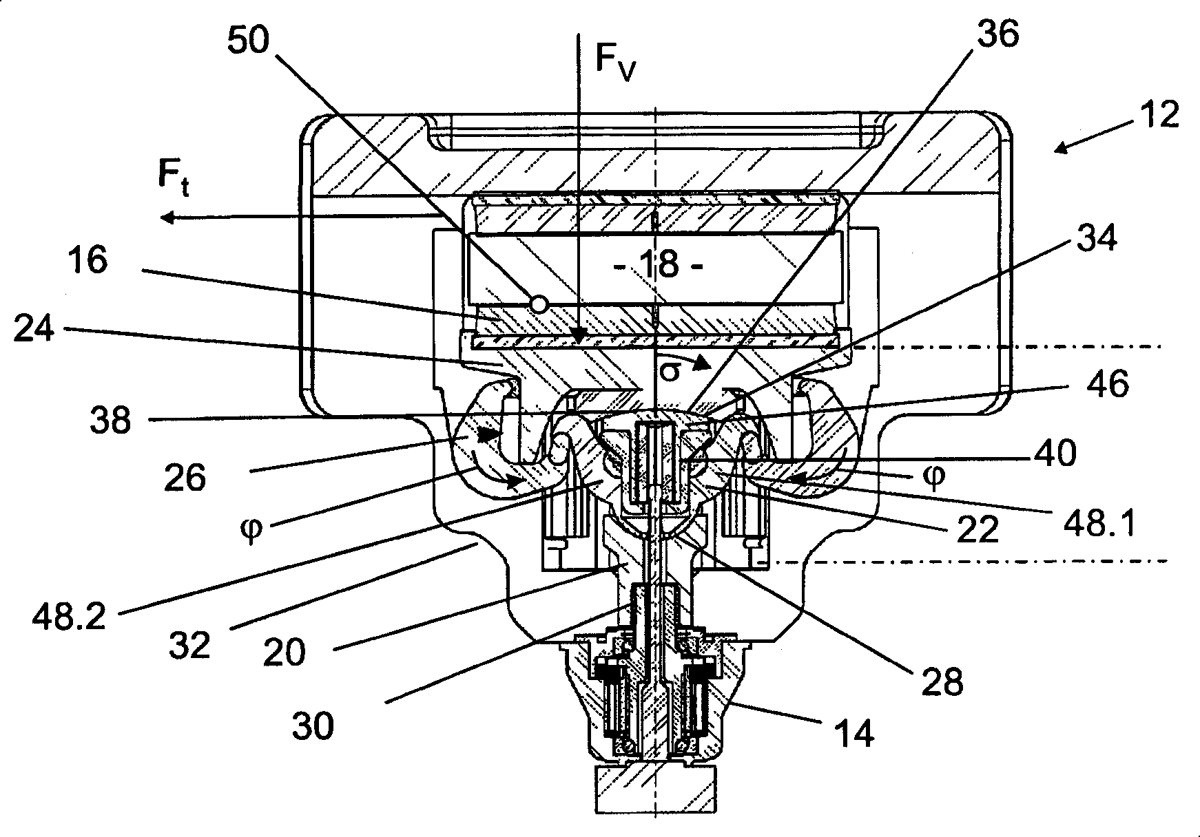
[0026] figure 1 A braking device 10 is shown with a brake 12 which is actuated by an actuator in the form of an electric drive 14 . The brake 12 has a brake shoe 16 which can be fed onto a brake disc 18 . To this end, the electric drive 14 applies the primary braking force F A (which can also be referred to as actuator force) is applied to the actuator-side component 20 . The actuator-side part 20 transmits the primary braking force to the coupling part 22 , which in turn transmits the primary braking force to the brake disc-side part 24 . The actuator-side part 20 , the coupling part 22 and the brake disc-side part 24 are components of the actuating element 25 .

[0027] If the brake disc 18 rotates at a rotational speed ω, and the brake shoe 16 comes into contact with the brake disc 18, a tangential force F t . As a result, the brake shoe 16 is slightly directed towards the tangential force F t direction of the displacement, and a force is applied to the first rod 26, ...


PUM


Abstract

The invention relates to a brake having a brake shoe (16), an actuating element for pressing the brake shoe (16) against a brake disc (18), and at least one lever (26) disposed such that it increases a braking force applied by the brake shoe (16) to the brake disc (18) by deflecting a tangential force acting on the brake shoe (16) during braking. The actuating element comprises at least one brake disc side part (24), an actuator side part (20), and a coupling part disposed between the brake disc side part and the actuator side part, wherein the coupling part (22) can be pivoted relative to the brake disc side part (24) and / or the actuator side part (20).

Description

technical field [0001] The invention relates to a brake having a brake shoe, an actuating element for pressing the brake shoe against a brake disc and at least one lever arranged in such a way that the lever is The tangential force acting on the brake shoe during actuation is diverted to increase the braking force applied by the brake shoe to the brake disc. Background technique [0002] A brake of this type is known from DE 10 2006 020 850 A1. In such a brake, a primary braking or actuator force is applied by the actuator to the operating element, so that the brake shoe is pressed against the brake disc. Once the brake shoe comes into contact with the brake disc, a tangential force is generated because the rotating brake disc drags the brake shoe with it. This tangential force is steered by the lever onto the actuating element and acts as a secondary braking force or auxiliary force which additionally presses the brake shoe against the brake disc. [0003] A disadvantage...

Claims


Application Information

Patent Timeline
Patent Type & Authority Patents(China)
IPC IPC(8): F16D55/22F16D65/18
CPCF16D2125/64F16D2127/10F16D2127/08F16D2121/24F16D65/18
Inventor 彼得·拜尔格哈德·布伦斯奥拉夫·扬茨哈特穆特·罗森达尔
Owner ZF CV SYST EURO BV
Why Eureka
Try Eureka