Tail safety brake device of motor vehicle

A technology for safe braking and motor vehicles, applied in the direction of brakes, braking components, vehicle parts, etc., can solve the problems of long emergency braking distance, achieve the effects of shortening braking distance, convenient disassembly and assembly, and reducing traffic safety accidents

Inactive Publication Date: 2011-07-27
刘成祥
View PDF6 Cites 5 Cited by
  • Summary
  • Abstract
  • Description
  • Claims
  • Application Information

AI Technical Summary

Problems solved by technology

[0003] Aiming at the limitation of the conventional braking ability of the motor vehicle in the above prior art, when the motor vehicle is running at high speed, the emergency braking distance is long, which leads to the occurrence of various traffic safety accidents, the present invention proposes a , It can improve the braking ability, shorten the braking distance, and enable the motor vehicle to realize emergency parking within a short distance, thereby reducing the safety braking device at the rear of the motor vehicle that occurs in various traffic accidents

Method used


Image

  • Tail safety brake device of motor vehicle
  • Tail safety brake device of motor vehicle
  • Tail safety brake device of motor vehicle

Examples


Embodiment 1

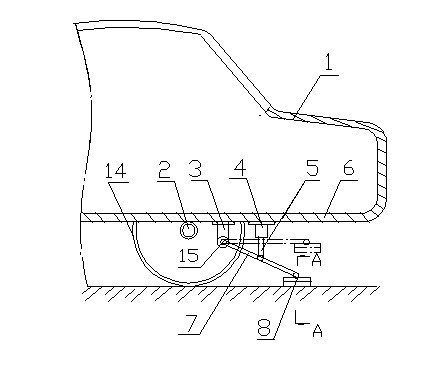
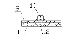
[0014] Example 1, in figure 1 with figure 2 Among them, the safety braking device at the rear of the motor vehicle includes a support 3, a pressure rod 7, a brake plate 8 and an ejector rod 5, and the support 3 is fixed on the rear bottom plate at the middle position near the rear of the rear axle 2 of the rear part 1 of the trolley 6, one end of the pressure rod 7 is movably connected with the support by a hinge shaft 15, the other end of the pressure rod is movably connected with the middle position of the support plate 9 on the brake plate 8 through the joint 10, and one end of the ejector rod 5 is movable in the middle of the pressure rod The other end of the ejector rod is connected to the oil cylinder 4, and the oil cylinder is fixed on the rear bottom plate. The brake plate includes a support plate 9 that is movably connected with the pressure rod and fixed on the support plate with several spaced apart screw rods 11. wear-resistant plate 12, the length of the support...

Embodiment 2

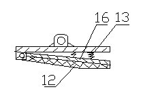
[0015] Example 2, in figure 1 with image 3 Among them, except that the structure of the brake plate is different from that of Example 1, other structures of Example 2 are the same as those of Example 1. The brake plate includes a support plate 9, a wear plate 12 and a lining plate 16, and the wear plate The plate is fixed on the liner with a screw rod and arranged obliquely. One end of the liner is movably connected with the support plate. A spring 13 is arranged between the liner and the support plate. The other end of the liner is separated from the support plate. The wear plate and the support plate are separated. The liner is arranged at an angle less than 15°, and the springs are arranged in one or two rows.

Embodiment 3

[0016] Example 3, in figure 1 with Figure 4 Among them, because the road surface of expressways, especially some provincial roads or national roads is not very smooth, in order to improve the auxiliary braking capability of the rear safety brake device of the present invention, except that the structure of the brake plate is the same as that of Embodiment 1 and Embodiment 1. 2, the other structure of embodiment 3 is the same as that of embodiment 1. The brake plate includes a support plate and a wear plate, and the wear plate 12 is composed of several small wear plates, and each small wear plate The springs 13 are fixedly connected with the support plate 9 respectively, and the wear-resistant plates are arranged longitudinally along the bottom plate of the tail,


PUM


Abstract

The invention discloses a tail safety brake device of a motor vehicle, which is installed at the tail part of the motor vehicle. The device comprises a support (3) and a pressure rod (7), wherein the support (7) is fixed at a tail bottom plate (6) or on a tail base frame; one end of the pressure rod (7) is moveably connected with the support and the other end of the pressure rod (7) is moveably connected with a brake plate (8); the brake plate comprises a support plate (9) and a wear-resistance plate (12) moveably fixed on the support plate; the pressure rod is moveably connected with an ejector rod (5) which makes the brake plate suspended when the motor vehicle runs normally and makes the wear-resistance plate on the brake plate tightly adhered to the pavement when the motor vehicle performs emergency brake; and the ejector rod is connected with a power unit. When the motor vehicle performs emergency brake during high-speed running, the friction force between the motor vehicle and the pavement can be increased, so that the brake capability is improved and the brake distance is shortened; and the emergency brake is realized in a relatively short distance which can be effectively controlled as far as possible, so various traffic accidents are reduced. The novel tail auxiliary safety brake device of the motor vehicle is compactly structured, reliable and safe to use and convenient to dismantle.

Description

technical field [0001] The invention relates to a motor vehicle braking device, in particular to a motor vehicle rear safety braking device. Background technique [0002] With the continuous development of the economy, great achievements have been made in the construction of highways and special expressways in our country. In recent years, provincial highways, national highways, and especially expressways have woven my country into a three-dimensional traffic with distinct backbones and crisscrossing lines. Internet. Due to the leveling of provincial roads, national roads, especially expressways, and the improvement of road management level and traffic management, the continuity of motor vehicles driving at high speed on roads has been greatly improved, and the number of emergency braking of motor vehicles has also been greatly reduced. Not only the driving efficiency of the motor vehicle is improved, the driving cost is reduced, but also the mechanical wear and energy consu...

Claims


Application Information

Patent Timeline
Patent Type & Authority Applications(China)
IPC IPC(8): B60T1/14
Inventor 刘成祥
Owner 刘成祥
Why Eureka
Try Eureka