
Extruding and extending device for horizontal loading drainage solidifying soft soil reinforcement and construction method thereof

A technology of drainage consolidation and horizontal loading, which is applied in the field of soft soil drainage consolidation and reinforcement method and squeeze-expanding device, can solve the problems of large post-construction settlement, long construction period, limited effective reinforcement depth, etc. amount of effect

Inactive Publication Date: 2011-07-27
BEIHANG UNIV
View PDF6 Cites 14 Cited by
  • Summary
  • Abstract
  • Description
  • Claims
  • Application Information

AI Technical Summary

Problems solved by technology

[0012] Aiming at the defects of the existing drainage consolidation method that a large amount of load needs to be transported in and out, the construction period is too long, the settlement after construction is large, and the effective reinforcement depth is limited, the invention proposes a horizontal loading drainage consolidation soft soil reinforcement method, which can achieve The purpose of shortening the drainage consolidation construction period and reducing post-construction settlement

Method used


Image

  • Extruding and extending device for horizontal loading drainage solidifying soft soil reinforcement and construction method thereof
  • Extruding and extending device for horizontal loading drainage solidifying soft soil reinforcement and construction method thereof
  • Extruding and extending device for horizontal loading drainage solidifying soft soil reinforcement and construction method thereof

Examples


Embodiment 1

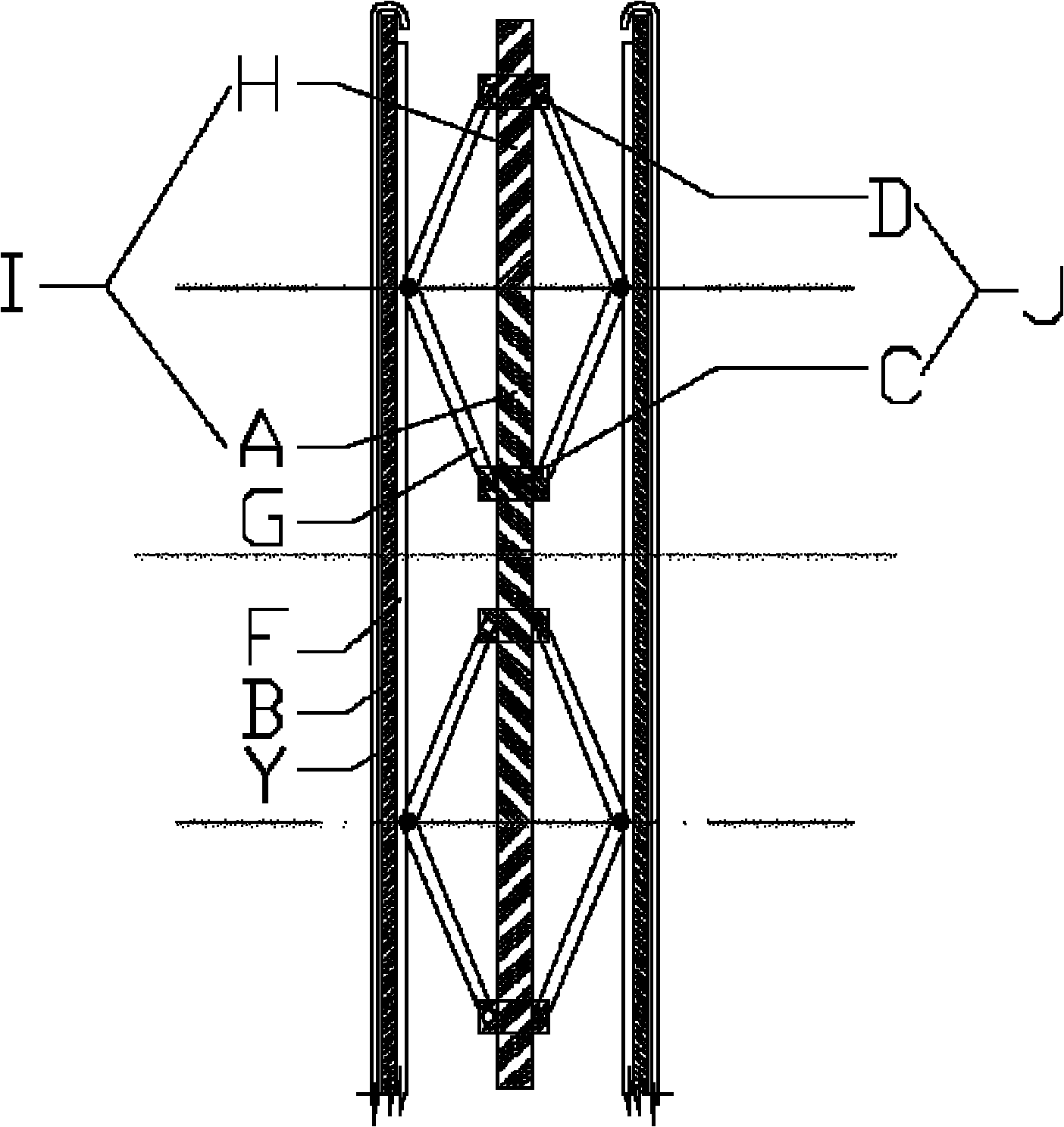
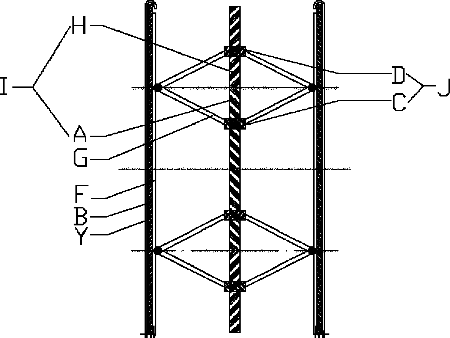
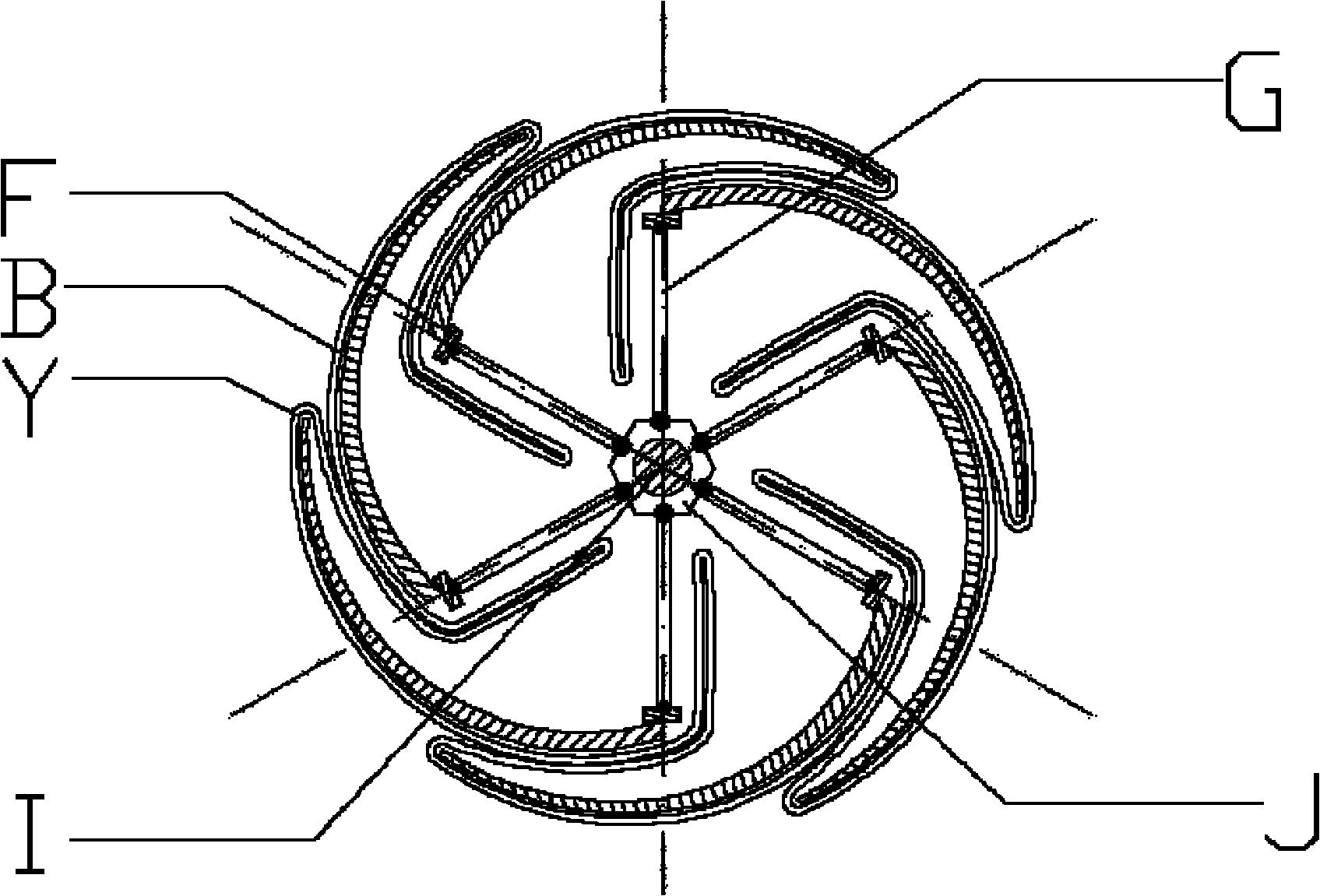
[0063] The soil layer of the project site is flow-plastic muddy clay. The extruder is made of aluminum alloy, the extruder adopts the whole plate method, and the expansion blade B adopts such as Figure 3a In the porous plate type shown, the holes 1 on the porous plate are evenly distributed, the permeable filter membrane Y is a wire mesh, and the permeable filter membrane Y is only welded to cover the hole 1 of the expanded blade B, as Figure 4b shown. The number of support rod pairs G and the support beams F and expansion blades B connected thereto is six. When the expander is in a contracted state, the diameter of the expander is 80mm, the diameter after expansion is 150mm, and the length of the expander is 10m. The distance between the expanders is 80cm, and the expanders in the shrinking state are pressed into the soil by static pressure. Rotate the central screw I of the extruder to expand the extruder to a diameter of 150mm by 2mm each time and once every 4 hours; d...

Embodiment 2

[0065]The soil layer of the project site is flow-plastic silty clay. The extruder is made of low-alloy carbon steel, and the number of support rod pairs G and connected support beams F and expansion blades B is 8. The extruder uses Figure 4c The half-plate form shown, that is, after the expansion blade B is fully expanded, one end of the expansion blade B is still connected to the support beam F, and the other end is a free end suspended in the air. The expansion blade B is used as follows: Figure 3b In the form of the grid shown, the grid form is a grid 2 evenly distributed in strips. The permeable filter membrane Y is a non-woven fabric reinforced with polymer fiber braided strips, and is made into a complete cylinder to cover the periphery of all expansion blades B of the expander and the soil layer in the gap between two adjacent expansion blades B The pressure is supported by the permeable membrane Y. The diameter of the expander is 100mm in the contracted state, and...

Embodiment 3

[0067] The soil layer of the project site is flow-plastic muddy silty clay. The extruder is made of high-strength engineering plastics, and the extruder is made of Figure 4d The form shown is the form without plates, the number of support rods G and the number of support beams F connected to them is 8; the permeable filter membrane Y is made of polymer fiber woven cloth, the diameter of the expander is 80mm in the contracted state, and the diameter after expansion is 80mm. 300mm, the design pile length is 20m. The space between the extruder 3 and the plastic drainage board 4 is arranged using Figure 5a Arrangement mode (triangular arrangement), the distance between the expanders is 300cm, and the expanders in the shrinking state are pressed into the soil by static pressure. Rotate the central screw of the extruder to expand the extruder to a diameter of 300mm by 5mm each time and once every 3 hours, drain the water in the pile hole formed by the extruder, and pour fluid ce...


PUM


Abstract

The invention discloses an extruding and extending device for horizontal loading drainage solidifying soft soil reinforcement and a construction method thereof, and belongs to the technical field of civil engineering. The extruding and extending device is formed by connecting a plurality of extruding and extending device units, wherein each unit consists of a central screw, a central nut pair, supporting rod pairs, a supporting beam and a water-permeable filter membrane; the central screw is formed by connecting a forward screw and a reverse screw; a forward nut and a reverse nut in the central nut pair are sleeved on the forward screw and the reverse screw respectively; the forward and reverse nut pair is hinged with a plurality of supporting rod pairs; the other end of each supporting rod pair is hinged to the supporting beam; and the water-permeable filter membrane is coated outside the supporting beam. The central screw of the extruding and extending device in a contraction state in soil is rotated to make the forward nut and the reverse nut move in opposite directions, the supporting rod pairs push the supporting beam and the water-permeable filter membrane to extend and extrude a soil body, and water in the soil is discharged to the extruding and extending device through the water-permeable filter membrane, so that the soil body is solidified; and the water in extruding and extending holes is drained, and an appropriate material is injected, so that construction is finished. By the extruding and extending device and the construction method thereof, the soil body is quickly solidified, and settlement after construction is reduced.

Description

technical field [0001] The invention relates to a soft soil drainage consolidation method in foundation treatment of buildings (structures), which belongs to the field of civil engineering, and specifically refers to a horizontal loading drainage consolidation soft soil reinforcement method and its application. Extruder. Background technique [0002] There is a large area of ​​soft soil in my country, especially in the eastern coastal areas where the economy is relatively developed, the population is dense, and the land resources are tight. The soft soil foundation needs to be reinforced before building (structure) structures. Drainage consolidation soft soil treatment technology is a foundation treatment technology with very low economic cost, so it is often the first choice for soft soil foundation treatment. At the same time, because this method does not use non-renewable resources, it is an environmentally friendly ground treatment method that conforms to the sustainabl...

Claims


Application Information

Patent Timeline
Patent Type & Authority Applications(China)
IPC IPC(8): E02D3/10
Inventor 黄新田雨宋冠中于浩
Owner BEIHANG UNIV
Learn More