
Guide cylinder structure applied on corrugated pipe expansion joint

A technology of guide tube and expansion joint, which is applied in the direction of expansion compensation device for pipelines, pipe components, pipes/pipe joints/fittings, etc., which can solve the problems of reducing the service life of bellows, increasing the service temperature of bellows, and using guide tubes. To avoid problems such as distortion and deformation, achieve the effect of reasonable design and simple structure

Inactive Publication Date: 2011-07-27
LUOYANG SUNRUI SPECIAL EQUIP
View PDF0 Cites 10 Cited by
  • Summary
  • Abstract
  • Description
  • Claims
  • Application Information

AI Technical Summary

Problems solved by technology

When the temperature of the pipeline medium is not too high, it can fully meet the requirements of use, but when the temperature difference between the inside and outside of the pipeline is very large, and there is a large temperature gradient change in the weld at the joint between the guide tube and the tube joint, the L-shaped guide tube and the tube The joint joint welds generally do not meet the stress assessment criteria, and the guide tube will generate huge circumferential stress due to thermal expansion, which will cause the entire guide tube to be distorted and deformed, resulting in cracking of the weld seam at the joint between the guide tube and the tube joint, resulting in isolation The heat layer is damaged, which further increases the service temperature of the bellows and reduces the service life of the bellows

Method used


Image

  • Guide cylinder structure applied on corrugated pipe expansion joint
  • Guide cylinder structure applied on corrugated pipe expansion joint
  • Guide cylinder structure applied on corrugated pipe expansion joint

Examples


Embodiment Construction

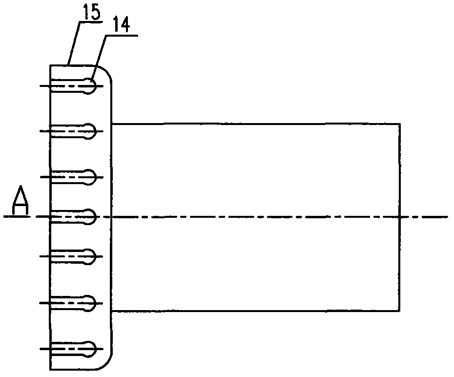
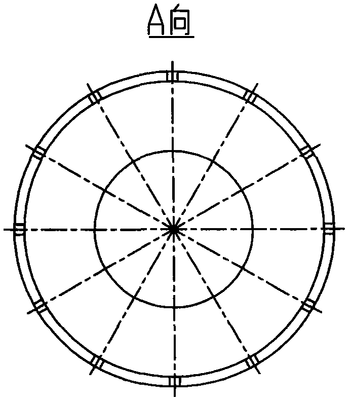
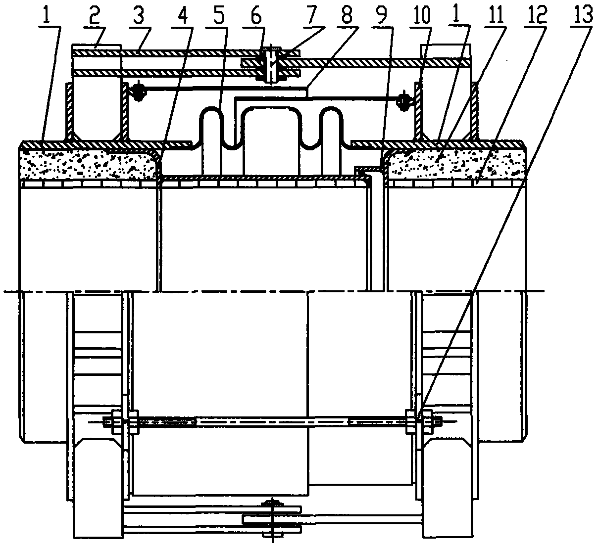
[0012] like figure 1 shown, combined with figure 2 , a guide tube structure applied to bellows expansion joints, the front end of the guide tube is a guide tube compensation ring 15 with a circular arc transition, and the outer surface of the guide tube compensation ring 15 is set There are 12 stress relief grooves 14 distributed along the circumference of the cylinder. The stress relief grooves 14 are consistent with the axial direction of the guide cylinder. The stress relief grooves 14 reduce the hoop stress generated by the guide cylinder due to thermal expansion, so that the flow guide The tubes 4 and 9 are not twisted and deformed; the arc section of the guide tube compensating ring of the guide tube is attached to the tube section of the bellows expansion joint, and the front end of the arc section is welded to the tube section of the expansion joint. When the guide tube is heated and expanded, the arc-shaped transition section absorbs the radial displacement and axia...


PUM


Abstract

The invention belongs to the technical field of petrochemical industry, and provides a guide cylinder structure applied on a corrugated pipe expansion joint. The front end of the guide cylinder is provided with a guide cylinder compensation ring (15); the outer side surface of the guide cylinder compensation ring (15) is provided with a plurality of distressing grooves (14) which are distributed along the circumference of a cylinder body; the distressing grooves (14) and the guide cylinder are axially consistent; the hoop stress generated by the heat expansion of the guide cylinder is reduced by the distressing grooves (14), thus the guide cylinder is not subjected to torsion and deformation; and the arc section of the guide cylinder compensation ring is jointed with the shell section of the corrugated pipe expansion joint, when the guide cylinder is expanded caused by heating, the arc transition section absorbs the radial displacement and axial displacement generated by the guide cylinder due to the expansion caused by heating, and absorbs the radial stress and axial stress generated by the guide cylinder due to the expansion caused by heating. According to the invention, through the distressing grooves distributed along the circumference of the cylinder body and the arc transition section of the cylinder body, thus the guide cylinder is not subjected to torsion and deformation when the guide cylinder works at high temperature, and the guide cylinder structure has the characteristics of reasonable design and simple structure.

Description

technical field [0001] The invention belongs to the technical field of petrochemical industry, and mainly relates to a guide cylinder structure applied to bellows expansion joints. Background technique [0002] The existing connection type between the guide tube and the tube joint used for the expansion joint of the high temperature lined structure is an L-shaped guide tube. When the temperature of the pipeline medium is not too high, it can fully meet the requirements of use, but when the temperature difference between the inside and outside of the pipeline is very large, and there is a large temperature gradient change in the weld at the joint between the guide tube and the tube joint, the L-shaped guide tube and the tube The joint joint welds generally do not meet the stress assessment criteria, and the guide tube will generate huge circumferential stress due to thermal expansion, which will cause the entire guide tube to be distorted and deformed, resulting in cracking o...

Claims


Application Information

Patent Timeline
IPC IPC(8): F16L51/02
Inventor 刘海威阎廷来姜雪桦王春会
Owner LUOYANG SUNRUI SPECIAL EQUIP
Learn More