
Device for measuring torque and power of photoelectric non-contact rotation shaft

A non-contact, power measurement technology, applied in the direction of measuring devices, torque measurement, power measurement, etc., can solve the problems of inability to overcome the drift of the trigger point of the detector, the inability to completely eliminate the system error, and the inability to eliminate the system error. Long-term online measurement application, elimination of trigger point drift, and convenient installation

Active Publication Date: 2011-07-27
WUHAN UNIV OF TECH
View PDF3 Cites 35 Cited by
  • Summary
  • Abstract
  • Description
  • Claims
  • Application Information

AI Technical Summary

Problems solved by technology

[0005] For the first system above, in order to obtain effective accuracy, it is necessary to ensure that the trigger points of the two sensors do not drift, and with the use of time and / or temperature changes, it is possible for the trigger points of the two sensors to drift relative to each other , and the two may even be in opposite directions
Although the second system uses a single detector to measure the laser signal emitted by a single light source, it can reduce the possible trigger point drift of the two detectors to some extent, but the change of the trigger point of the single detector itself with temperature drift cannot be measured. Compensated, so it is impossible to completely eliminate this systematic error
In addition, the second system adopts an optical modulation structure. This method of modulating light into a pulse signal and then outputting it will also have a certain delay, because a certain amount of systematic error that cannot be eliminated will be introduced into the system.
From these points, neither of the two torque measurement systems can overcome the trigger point drift caused by the characteristic change of the detector itself

Method used


Image

  • Device for measuring torque and power of photoelectric non-contact rotation shaft
  • Device for measuring torque and power of photoelectric non-contact rotation shaft
  • Device for measuring torque and power of photoelectric non-contact rotation shaft

Examples


Embodiment Construction

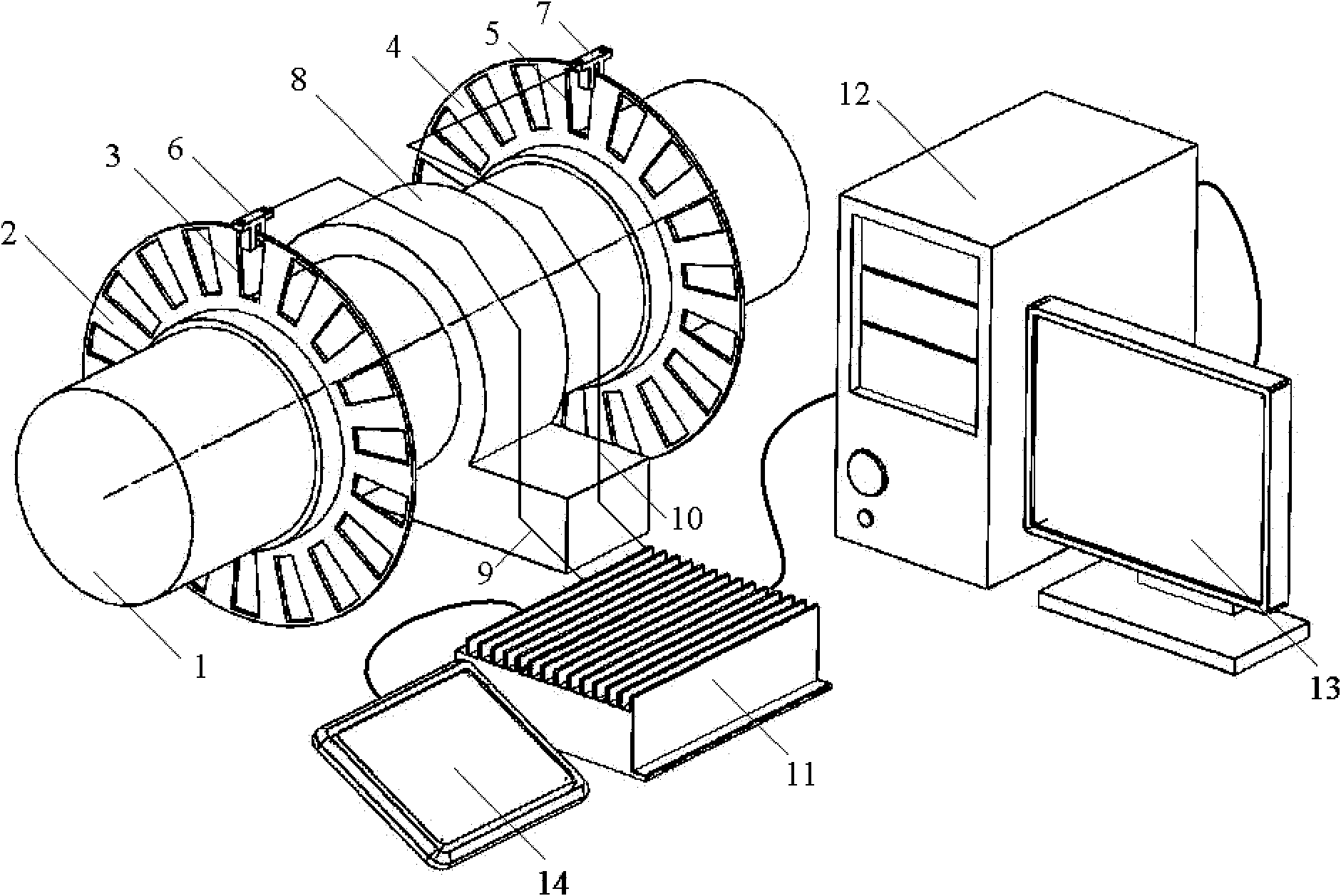
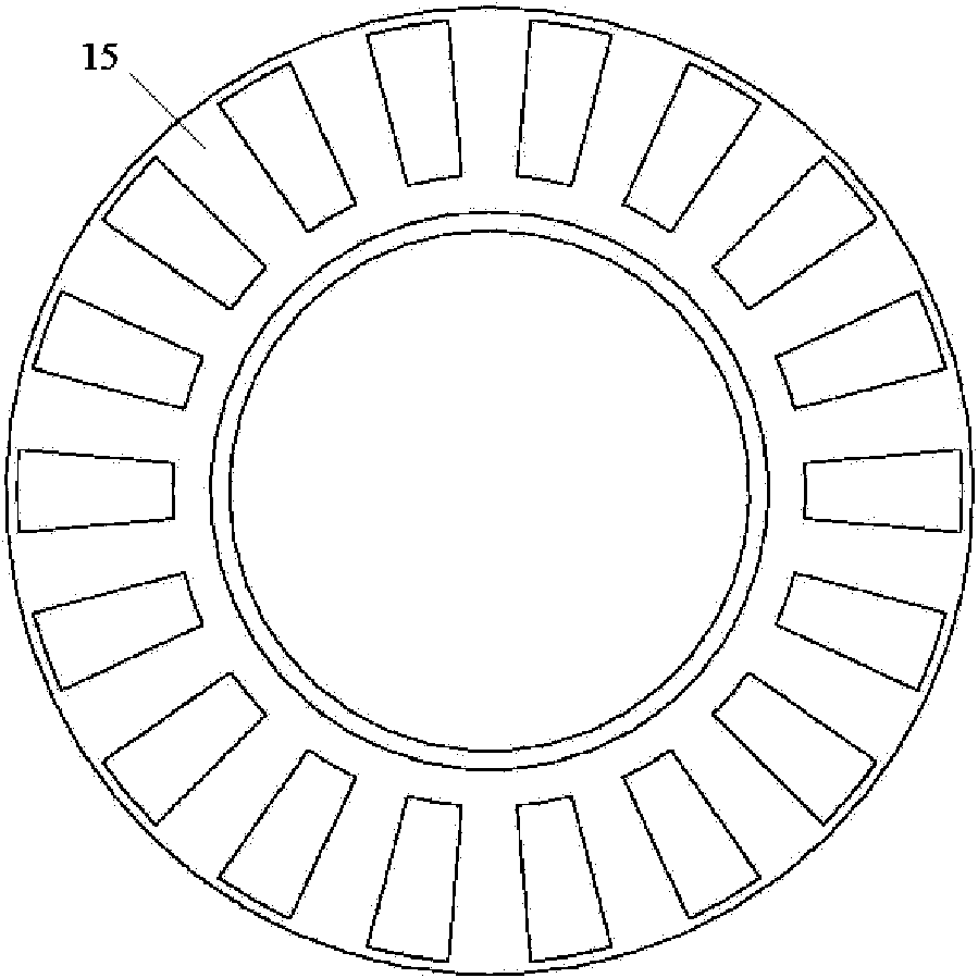
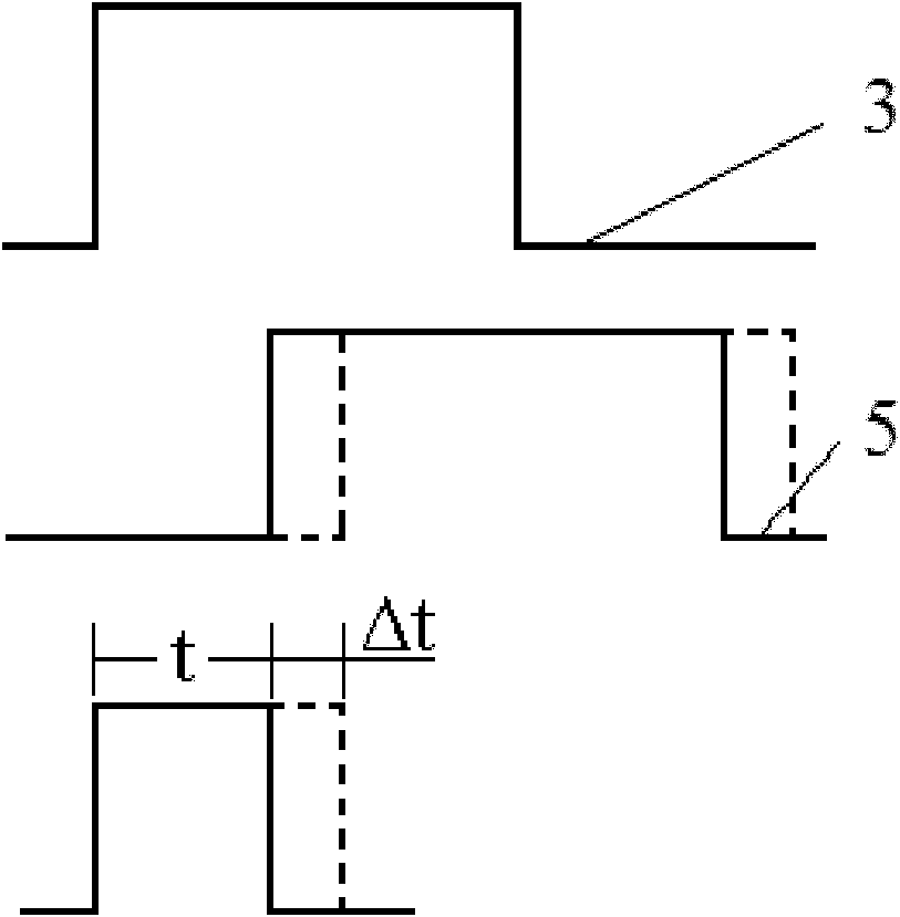
[0029] The photoelectric non-contact rotating shaft torque and power measuring device proposed by the present invention adopts two gear discs or photoelectric encoder discs installed at an appropriate distance on the measured rotating shaft, and the two photoelectric codes are used during the rotation of the measured rotating shaft. The discs are swept across the corresponding high-speed photoelectric switches to generate electrical pulse output. When a load is added to the rotating shaft to be tested, the rotating shaft will intensify its torsion, and a small relative torsion will occur between the two gear discs. By detecting the phase difference between the two pulses output by two photoelectric encoders, the torsion angle of the measured rotating shaft can be calculated. When this angle is calculated, when the rotational speed is also measured or known, the torque and power of the rotating shaft can be calculated.

[0030] The invention also provides a logical calculation...


PUM


Abstract

The invention relates to a device for measuring a torque and power of a photoelectric non-contact rotation shaft. The device mainly consists of a controller (11), a computer (12), at least two photoelectric encoders and photoelectric switches, wherein the photoelectric encoders are arranged on a measured rotation shaft (1); each photoelectric encoder corresponds to one photoelectric switch and is provided with a plurality of uniformly distributed transparent holes and a light barrier; the computer is connected with the output interface of the controller through a serial data wire; the measurement signal input end of the controller is connected with the photoelectric switches through lead wires respectively; and signals output from all the photoelectric switches are logically calculated and processed in the controller, and transmitted to the computer so as to display curves of the torque and the power with the time variation in a display (13) or a liquid crystal screen (14). The device for measuring the torque and the power of the photoelectric non-contact rotation shaft can be used for online measurement for long time and is not contacted with the measured rotation shaft, so errors caused by the measurement environment can be restrained; and the device is convenient to install, can be widely used and has the advantages of high precision and durable stability.

Description

technical field [0001] The invention relates to a measuring device, in particular to a photoelectric non-contact rotating shaft torque and power measuring device. Background technique [0002] Of the methods that have been used to measure power on rotating shafts of various types of machinery, a large number rely on the way strain gauges are attached to the rotating shaft. The transmission methods of strain gauge signals mainly include slip rings and telemetry methods. The slip ring can ensure that the strain gauge signal is transmitted to the acquisition circuit uninterruptedly when the shaft rotates. The telemetry method needs to install a transmitter on the rotating shaft to provide power by rotating the battery, and the transmitter transmits the current change of the strain gauge to the collection electronic circuit through a wireless signal. [0003] Some newer systems now use Hall sensors. This solution generally installs two large gears at a certain distance on the...

Claims


Application Information

Patent Timeline
IPC IPC(8): G01L3/04G01L3/24
Inventor 杨琨周新聪严新平
Owner WUHAN UNIV OF TECH
Learn More