Method for testing vibration mode

A testing method and vibration mode technology, applied in vibration testing, testing of machine/structural components, measuring devices, etc., can solve the problems of poor effectiveness, low reliability of test data, low efficiency, etc., to reduce testing costs and improve The effect of identifying accuracy and reliability and shortening the test cycle

Inactive Publication Date: 2011-07-27
AECC AVIATION POWER CO LTD
View PDF1 Cites 31 Cited by
  • Summary
  • Abstract
  • Description
  • Claims
  • Application Information

AI Technical Summary

Problems solved by technology

[0007] In order to overcome the deficiencies of low reliability, low efficiency and poor effectiveness of test data when relying on experience to select the

Method used


Image

  • Method for testing vibration mode
  • Method for testing vibration mode
  • Method for testing vibration mode

Examples


Embodiment 1

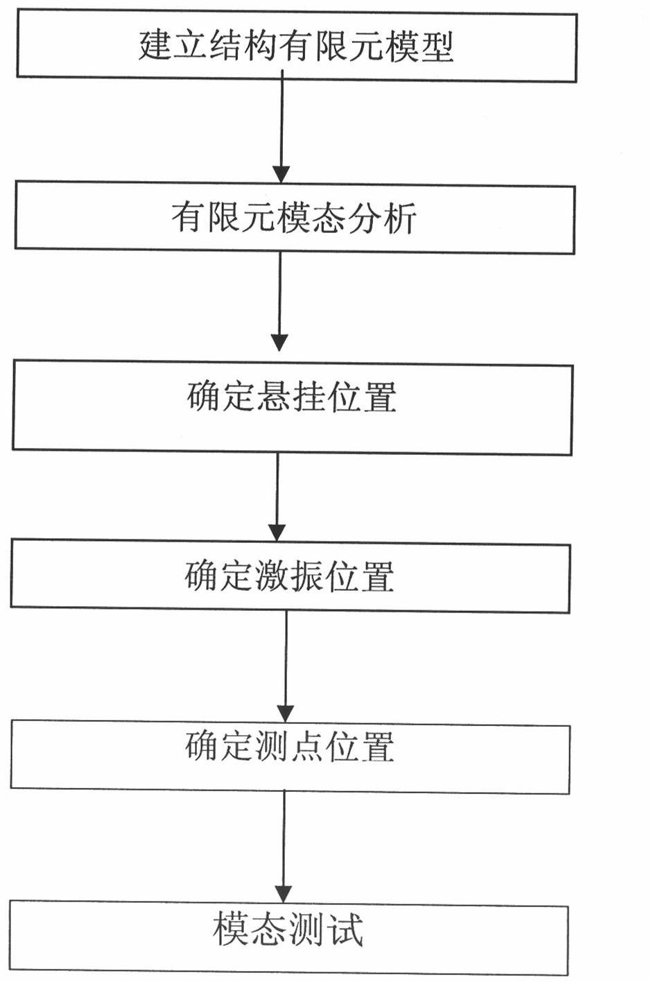
[0054] This embodiment is a modal test method for a flat plate proposed based on the finite element method. The flat plate is 0.14m long, 0.06m wide, and 0.002m thick. The method adopts the optimized suspension position, excitation position and measuring point position to realize the modal test of the plate structure. The specific implementation process of this embodiment includes the following steps:

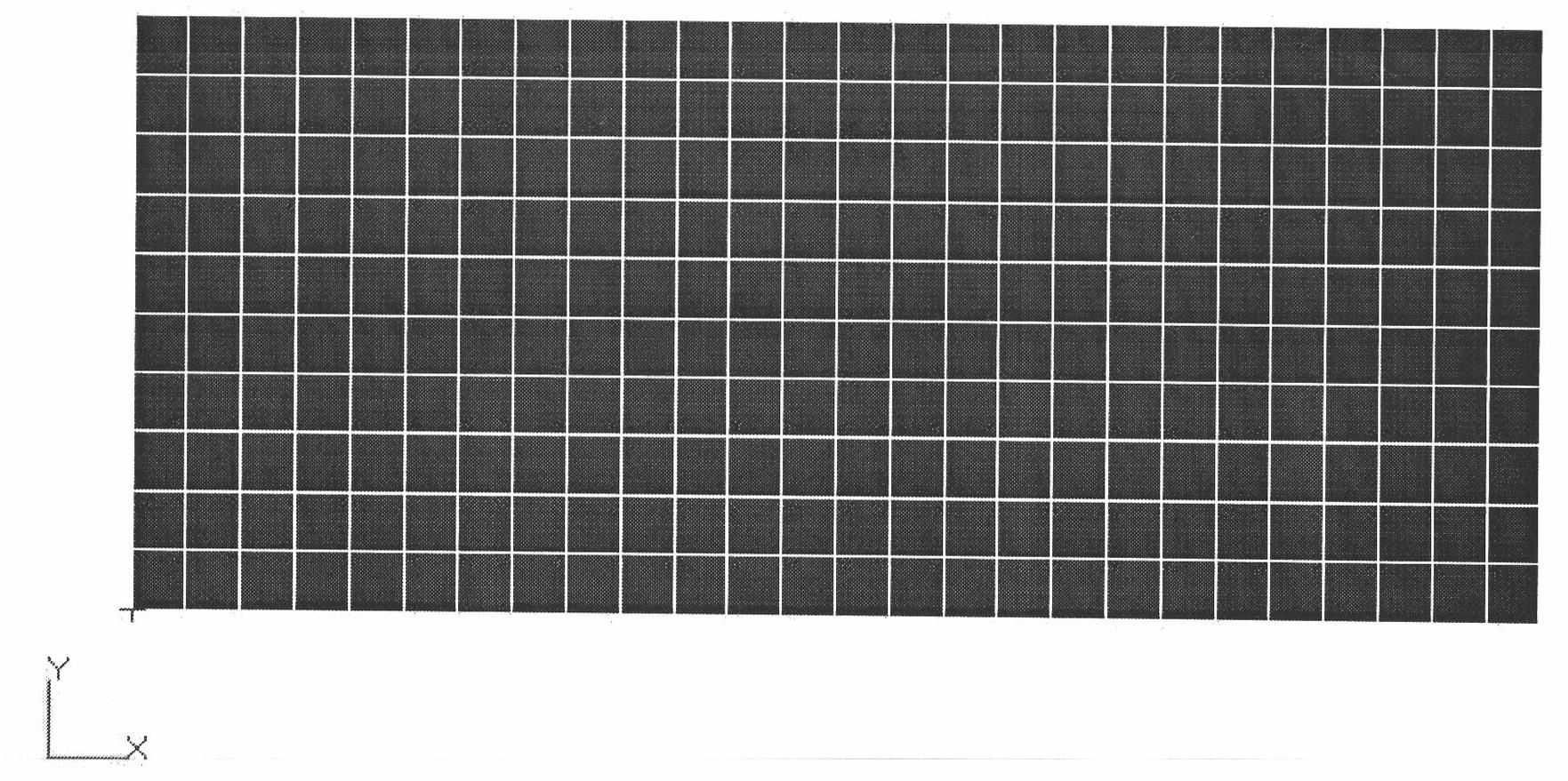
[0055] Step 1. See figure 2 A two-dimensional plate model of the plate structure was established in the commercial finite element software Patran.

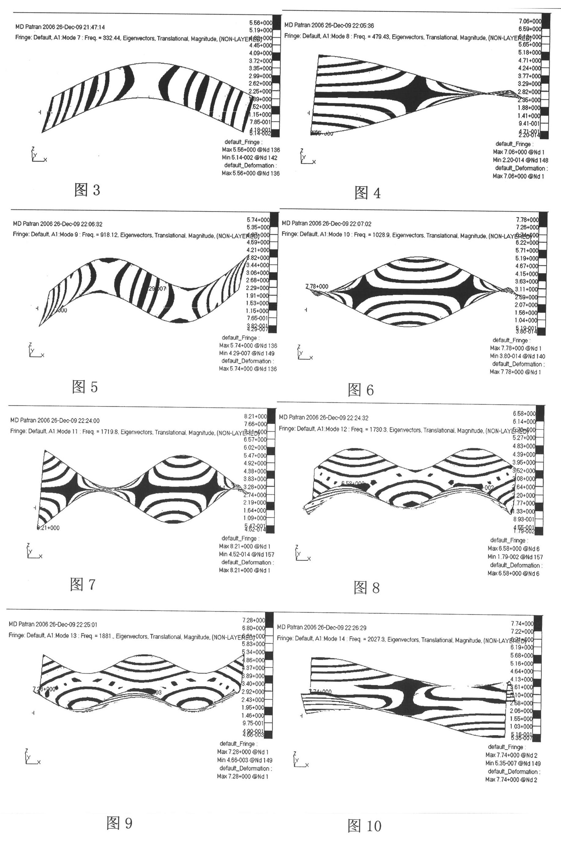
[0056] Step 2. Divide the finite element grid of the plate; the plate is taken from the boundary conditions; define the material and unit physical characteristics of the plate; submit the task and use the commercial finite element software Nastran to perform the normal mode analysis of the plate to obtain the first 20 modes of the plate. Since the first six modes of the plate are rigid body modes, they are not considered. For t...

Embodiment 2

[0089] This embodiment is a modal test method for a flat plate proposed based on the finite element method. The flat plate is 0.14m long, 0.06m wide, and 0.002m thick. The method adopts the optimized suspension position, excitation position and measuring point position to realize the modal test of the plate structure. The specific implementation process of this embodiment includes the following steps:

[0090] Step 1. See figure 2 A two-dimensional plate model of the plate structure was established in the commercial finite element software Patran.

[0091] Step 2. Divide the finite element grid of the plate; the plate is taken from the boundary conditions; define the material and unit physical characteristics of the plate; submit the task and use the commercial finite element software Nastran to perform the normal mode analysis of the plate to obtain the first 20 modes of the plate. Since the first six modes of the plate are rigid body modes, they are not considered. For t...


PUM


Abstract

The invention discloses a method for testing a vibration mode. The method comprises the following steps of: determining the optimal hanging position, the optimal excitation position and the optimal testing point during structure mode test by establishing a finite element model of the structure and analyzing the finite element model; during excitation position determination, providing two corresponding methods for determining the excitation position respectively as for excitation by an exciter method and excitation by a hammering method; and finally, hanging the structure to be tested at the determined optical hanging position, exciting the structure at the determined excitation position by the hammering method or the exciter method, and arranging a sensor to perform the mode test on the structure at the determined testing point position. By the method, the identification precision and the reliability of mode parameters can be improved effectively, the test cost is reduced, and the test cycle is shortened.

Description

technical field [0001] The invention relates to the field of structural vibration modal testing, in particular to a vibration modal testing method. Background technique [0002] For a long time, when conducting structural vibration modal experiments, how to hang the test structure, select the position of the excitation point, select the number of test sensors and the test position on the structure mainly depends on the experience of the technicians, which directly affects the structure. Accuracy and reliability of vibration modal test data. [0003] The boundary condition commonly used in structural vibration modal tests is the free-free boundary condition. Theoretically, under the free-free boundary condition, the structure under test cannot be attached to any objects, which is difficult to achieve in practice. Usually, the "free-free" boundary conditions in practical tests are approximated, and this approximation can be achieved by hanging with soft springs or rubber cor...

Claims


Application Information

Patent Timeline
IPC IPC(8): G01M7/02G06F17/50
Inventor 刘忠华臧朝平陈伟王晓伟苗向蒋学军阎志祥杨东
Owner AECC AVIATION POWER CO LTD
Why Eureka
Try Eureka