Automatic bearing inside diameter detector

An automatic detection and bearing inner ring technology, applied in instruments, measuring devices, sorting, etc., can solve the problems of high cost, difficulty in ensuring reliability, low efficiency of bearing inner diameter detection, etc., and achieve the effect of ensuring reliability

Inactive Publication Date: 2011-08-03
绍兴中轴自动化设备有限公司
0 Cites 37 Cited by

AI-Extracted Technical Summary

Problems solved by technology

[0003] In order to overcome the problems of low efficiency, difficulty in ensuring reliability and high cost of existing bearing inner diameter detection, the present invention provides a sensor-based automatic b...

Abstract

The invention discloses an instrument capable of implementing automatic detection and sorting of bearing inside diameter. A double-path symmetrical structure is adopted, an inlet sorting mechanism is fixed on one side of a conveyor belt, the side of the conveyor belt is provided with a feeding cylinder and a feeding rod, the other side of the conveyor belt is provided with a station, the station is provided with a station clamping plate and a push plate which are fixed on a station clamping cylinder, the station clamping cylinder is fixed on a station push cylinder, one side of the station is provided with an inside diameter detection mechanism, the station is provided with two gaps which are communicated with a reject outlet and a repair outlet respectively, a reject zone baffle plate and a repair zone baffle plate are arranged on the two gaps respectively, an outlet sorting hopper is fixed at one end of the station, an outlet sorting block is arranged below the outlet sorting hopper, the outlet sorting block is fixed on an outlet sorting cylinder, two sides of the outlet sorting block are provided with an outlet push cylinder and a small groove respectively, and two sides of the small groove are provided with a discharge plate and a discharge frame respectively. The instrument can ensure the reliability of detection on the premise that the detection efficiency of the bearing inside diameter is not reduced, and realizes automation of feeding, detection and sorting.

Application Domain

Technology Topic

Image

  • Automatic bearing inside diameter detector
  • Automatic bearing inside diameter detector
  • Automatic bearing inside diameter detector

Examples

  • Experimental program(1)

Example Embodiment

[0015] The present invention will be further described below in conjunction with the drawings and embodiments.
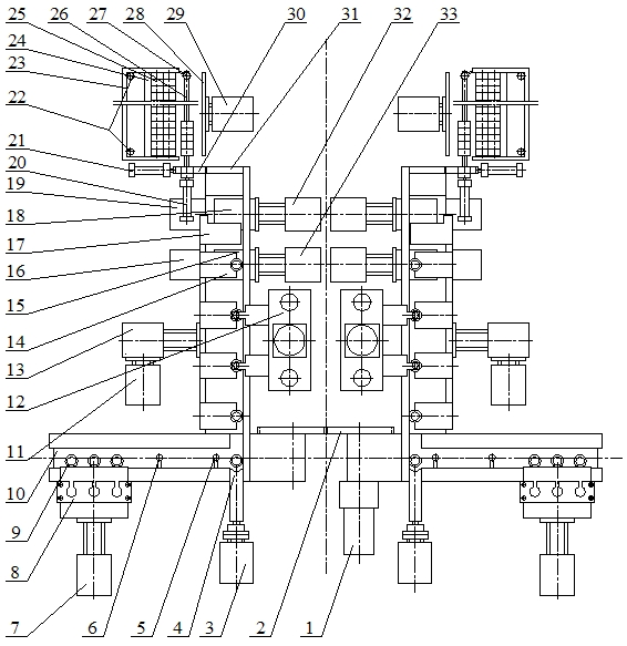
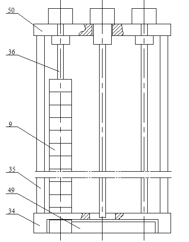
[0016] Such as figure 1 , Figure 4 As shown, the inner ring 9 of the bearing to be inspected is installed on the imported material distributing mechanism 8. The imported material distributing mechanism 8 can push the inner ring 9 of the bearing to be inspected onto the conveyor belt 10 at a certain beat. The two conveyor belts 10 on the left and right are driven by the conveyor motor 1 Driven by the meshing gear set 2, the feed detection switch 6 and the lack detection switch 5 are arranged above the conveyor belt 10. The feed detection switch 6 and the lack detection switch 5 are fixed on the equipment base on the side of the conveyor belt 10, and the feeding cylinder 3 is fixed on On the equipment base on the side of the conveyor belt 10, a feeding rod 4 is fixed on the piston rod of the feeding cylinder 3, and the feeding rod 4 is close to the upper surface of the conveyor belt 10. A station 48 is set on the other side of the conveyor belt 10. The cross section of the station 48 is In the horizontal "L" shape, one end of the station 48 is as high as and close to the conveyor belt 10. The raised part of the station 48 extends to the conveyor belt 10, and there are four clamping plates above the table of the station 48 14 and one push block 17, four station clamping plates 14 and one push block 17 are all fixed on the piston rod of the station clamping cylinder 13, and the four station clamping plates 14 are equally spaced. The clamping cylinder 13 is fixed on the piston rod of the station pushing cylinder 11, and the station pushing cylinder 11 is fixed on the equipment underframe on the side of the station table 48. There are two notches on the table surface of the station table 48, and they are scrapped. The exit 16 and the repair exit 19 are connected, and a scrap area baffle 15 is set at the gap connected with the scrap outlet 16. The surface of the scrap area baffle 15 and the table surface of the station 48 are equal, and the scrap area baffle 15 is fixed on the piston rod of the execution cylinder 33 in the scrap area, and the execution cylinder 33 in the scrap area is fixed on the equipment chassis. Similarly, a repair area baffle 18 is provided at the gap of the station 48 connected with the repair outlet 19, The board surface of the rework area baffle 18 is flush with the table surface of the station 48. The rework area baffle 18 is fixed on the piston rod of the rework area executive cylinder 32, and the rework area executive cylinder 32 is fixed on the equipment chassis. The other side of the table 48 is provided with an inner diameter detection mechanism 12, the inner diameter detection mechanism 12 is fixed on the equipment chassis, the other end of the station table 48 is fixed with an outlet dividing hopper 31, and an outlet dividing block 30 is provided under the outlet dividing hopper 31. The distribution block 30 is fixed on the piston rod of the outlet distribution cylinder 21, and the outlet distribution cylinder 21 is fixed on the equipment chassis. There is a small gap on the outlet distribution block 30. When the piston rod of the outlet distribution cylinder 21 extends When the gap is aligned with the bottom of the outlet distribution hopper 31, when the piston rod of the outlet distribution cylinder 21 is retracted, the gap is aligned with the axis of the piston rod of the outlet pushing cylinder 20, and the outlet pushing cylinder 20 is fixed on the equipment chassis In the direction of the piston rod axis of the outlet pushing cylinder 20, a small groove 26 is also provided. The small groove 26 is fixed on the equipment chassis. The qualified bearing inner ring 25 is arranged on the small groove 26. One end of the tank 26 is close to the outlet dividing block 30, and a discharge detection switch 27 is arranged above the other end. The discharge detection switch 27 is fixed on the discharge frame 23, and the discharge frame 23 is fixed on the equipment chassis. Placed in the material frame 23 is a whole row of Grid bearing inner ring 25 and a stopper 24. The stopper 24 is floating and is not fixed. Two full detection switches 22 are fixed above the two corners of the discharge frame 23 to detect the discharge frame 23. Whether the interior is full of materials, a discharge plate 28 is provided on one side of the small groove 26. The discharge plate 28 is fixed on the discharge cylinder 29, and the discharge cylinder 29 is fixed on the equipment chassis. In order to improve the detection efficiency, the The invention adopts dual-channel simultaneous detection.
[0017] Such as figure 1 , figure 2 As shown, the imported material distributing mechanism 8 includes an imported material distributing cylinder 7, a material distributing push plate 49, a material rod fixing lower seat 34, a material rack support rod 35, a material rod 36 and a material rod fixing upper seat 50, and a bearing to be inspected The inner ring 9 is stringed on the material rod 36. Several material rods 36 are hung side by side on the material rod fixed upper seat 50. The lower end of the material rod 36 leads to the blanking hole of the material rod fixed lower seat 34. The inner ring 9 of the bearing to be inspected is under gravity. Under the action of, the blanking hole of the lower seat 34 fixed by the material rod falls into the recessed groove of the lower seat 34 of the material rod fixed, and the upper material rod fixing seat 50 is fixed on the lower material rod fixing seat 34 through the material rack support rod 35. The lower base 34 of the material rod fixing is fixed on the equipment underframe, the imported material distributing cylinder 7 is fixed on the equipment underframe, and the material distributing push plate 49 is fixed on the piston rod of the imported material distributing cylinder 7. The rods travel back and forth in the reverse buckle grooves of the lower seat 34, and the distributing push plate 49 is close to the top of the conveyor belt 10.
[0018] Such as figure 1 , image 3 As shown, the inner diameter detection mechanism 12 includes an X-direction inner diameter detection sensor 37, a guide rod 38, a lifting platform 39, a nut 40, a motor fixing platform 41, a lifting motor 42, a detection switch adjustment piece 43, a lead screw 44, and a calibration zero. Position switch 45, measurement zero switch 46 and Y-direction inner diameter detection sensor 47, X-direction inner diameter detection sensor 37 and Y-direction inner diameter detection sensor 47 are arranged above the station 48, X-direction inner diameter detection sensor 37 and Y-direction inner diameter detection The distance between the sensors 47 is the same as the distance between the station clamping plates 14. The X-direction inner diameter detection sensor 37 and the Y-direction inner diameter detection sensor 47 are both fixed on the lifting platform 39, and a nut 40 is also fixed on the lifting platform 39. A guide rod 38 is passed through the lifting platform 39. The lifting platform 39 can slide freely up and down along the guide rod 38. The lower end of the guide rod 38 is fixed on the equipment chassis, the upper end is fixed with a motor fixing plate 41, and the motor fixing plate 41 is fixed with a lifter. A screw 44 is fixed on the rotating shaft of the motor 42 and the lifting motor 42. The screw 44 and the nut 40 fixed on the lifting platform 39 are screw-fitted.
[0019] The working principle of the present invention is as follows:
[0020] In order to improve the detection efficiency, the present invention adopts a dual-path simultaneous detection method. The working principle of each path is the same. The inner ring 9 of the bearing to be inspected is stringed on the material rod 36, and the inner ring 9 of the bearing to be inspected passes the material under the action of gravity. The blanking hole of the rod fixing lower seat 34 falls into the back buckle groove of the rod fixing lower seat 34, because the height of the back buckle groove of the rod fixing lower seat 34 is only slightly higher than the thickness of the bearing inner ring 9 to be inspected Therefore, only the bottom inner ring 9 of the bearing to be inspected is allowed to completely fall into the recessed groove of the lower seat 34 of the material rod and be completely separated from the material rod 36. When the piston rod of the imported material distribution cylinder 7 is extended, The distribution push plate 49 is fed into the reverse buckle groove of the lower seat 34 of the material rod fixing, thereby pushing the bottom bearing inner ring 9 to be inspected onto the conveyor belt 10. When the piston rod of the imported material distribution cylinder 7 contracts, The distributing push plate 49 retracts and exits the back-locking groove of the lower seat 34 of the material rod fixing, and a new bearing inner ring 9 to be inspected falls into the back-locking groove of the lower seat 34 of the material rod fixing. Controlling the movement frequency of the piston rod of the imported material distribution cylinder 7 can control the material distribution speed. The conveyor motor 1 drives the rotation of the meshing gear set 2, thereby driving the movement of the left and right conveyor belts 10. By adjusting the rotation speed of the conveyor motor 1, you can Adjust the moving speed of the conveyor belt 10. When the conveyor belt 10 conveys the inner ring 9 of the bearing to be inspected, it passes under the feed detection switch 6 and the shortage detection switch 5 one after another. Normally, there is always a bearing to be inspected under the shortage detection switch 5 If the inner ring 9 is present, otherwise the shortage alarm will be activated. When the inner ring 9 of the bearing to be inspected under the feed detection switch 6 exists, the imported material distribution mechanism 7 will not operate, and there is no inner ring of the bearing to be inspected under the feed detection switch 6 When 9 exists, the imported material distribution mechanism 7 will act, and the conveyor belt 10 will send the inner ring 9 of the bearing to be inspected to the front of the feeding rod 4, which is blocked by the protrusion of the station 48. When the piston rod of the feeding cylinder 3 is extended , The feeding rod 4 pushes a bearing inner ring 9 to be inspected to the first station of the station 48. At this time, the station pushes the cylinder 11 to contract, and then the station clamps the cylinder 13 to extend, and the first station The inner ring 9 of the bearing to be inspected on the upper part is clamped between the protrusion of the station 48 and the gap of the clamping plate 14 of the station, and then the station pushes the cylinder 11 to extend, and the inner ring of the bearing to be inspected on the first station 9 is sent to the second station of the station table 48. At this time, the lifting motor 42 drives the screw 44 to rotate, so that the nut 40, the lifting table 39, the X-direction inner diameter detection sensor 37 and the Y-direction inner diameter detection sensor 47 move downward , Move to a certain position and stop, the Y-direction inner diameter detection sensor 47 extends into the hole of the bearing inner ring 9 to be inspected, measures the Y-direction inner diameter on the first section of the bearing inner ring 9 to be inspected, and then the lifting motor 42 drives the lead screw 44 continues to rotate, the Y-direction inner diameter detection sensor 47 continues to descend until the measuring zero switch 46 senses the lifting platform 39 to measure the Y-direction inner diameter on the second section of the bearing inner ring 9 to be inspected, and then the lifting motor 42 drives the wire The bar 44 is reversed, and the Y-direction inner diameter detection sensor 47 moves upward with the lifting platform 39 until the calibration zero switch 45 senses the lifting platform 39. At this time , The station chucking cylinder 13 shrinks, then the station pushing cylinder 11 shrinks, and then the station chucking cylinder 13 extends, repeating the previous action, and the inner ring of the bearing to be inspected on the first station of the station 48 9 Push to the second station, push the inner ring 9 of the bearing to be inspected on the second station of the station 48 to the third station, and push the third station to the fourth In the station, the fourth station is pushed to the fifth station. When the bearing inner ring 9 to be inspected is on the third station of the station 48, it is similar to the second station. 39 is lowered twice, the X-direction inner diameter detection sensor 37 measures the X-direction inner diameters on the two different sections of the bearing inner ring 9 to be inspected. In this way, through the numerical calculation of the inner diameters of the different sections, the inner hole taper of the bearing inner ring 9 to be inspected can be calculated , Through the numerical calculation of X-direction inner diameter and Y-direction inner diameter, the inner hole roundness of the bearing inner ring 9 to be inspected can be calculated, and the measured and calculated inner diameter value, taper value and roundness value are respectively carried out with the set value Based on this, it is determined whether the bearing inner ring 9 to be inspected is a qualified part, a scrapped part or a reworked part. If it is a scrapped part, when the bearing inner ring 9 to be inspected is pushed to the fourth station of the station 48, the scrap area When the baffle 15 is on top, the cylinder 33 in the scrap area is contracted, and the baffle 15 in the scrap area is pulled open, so that the bearing inner ring 9 to be inspected falls into the gap in the scrap area of ​​the station table 48, and then falls out of the scrap exit 16. If the bearing inner ring 9 to be inspected is not a scrapped part, but a reworked part, when the bearing inner ring 9 to be inspected is pushed to the fourth station of the station table 48, the cylinder 33 in the scrapped area does not act, that is, it keeps extending In the long state, the inner ring 9 of the bearing to be inspected will continue to be sent to the fifth station, which is above the baffle 18 in the rework area. The execution cylinder 32 of the rework area is contracted, and the baffle 18 of the rework area is pulled apart to make the bearing The ring 9 falls into the gap in the repair area of ​​the station 48, and then falls out of the repair exit 19. If the inner ring 9 of the bearing to be inspected is a qualified part, the cylinder 32 in the repair area will not operate in the fifth station. That is, the extended state is maintained. When the cylinder 11 is extended at the station, the pushing block 17 pushes the inner ring 9 of the bearing to be inspected into the outlet hopper 31. At this time, the inner ring of the bearing to be inspected 9 is converted into a qualified bearing inner ring 25. When the outlet dividing cylinder 21 is extended, the gap of the outlet dividing block 30 is aligned with the bottom of the outlet dividing hopper 31, a qualified bearing inner ring 25 falls into the gap of the outlet dividing block 30, and then the outlet dividing cylinder 21 shrinks , And then the outlet pushing cylinder 20 extends, pushing the qualified bearing inner ring 25 that fell into the gap of the outlet dividing block 30 into the small groove 26, and so on, the qualified bearing inner ring 25 in the outlet dividing hopper 31 It is gradually pushed into the small groove 26 for arrangement. When the qualified bearing inner ring 25 in the small groove 26 is arranged below the discharge detection switch 27, the discharge cylinder 29 is extended, and the discharge plate 28 pushes the small groove 26 The middle row of qualified bearing inner rings 25 into the discharge frame 23. The stopper 24 in the discharge frame 23 is used to maintain the orderliness of the entire row of qualified bearing inner rings 25. When the stopper 24 is pushed to the full material When the bottom of the switch 22 is detected, the full material alarm of the system will be triggered to indicate The user immediately processes the material in the discharge frame 23.

PUM

no PUM

Description & Claims & Application Information

We can also present the details of the Description, Claims and Application information to help users get a comprehensive understanding of the technical details of the patent, such as background art, summary of invention, brief description of drawings, description of embodiments, and other original content. On the other hand, users can also determine the specific scope of protection of the technology through the list of claims; as well as understand the changes in the life cycle of the technology with the presentation of the patent timeline. Login to view more.

Similar technology patents

Classification and recommendation of technical efficacy words

Why Eureka
Try Eureka