Flux-cored wire belt type powder feeder

A flux-cored welding wire and belt-type technology, which is applied to conveyors, conveyor objects, transportation and packaging, etc., can solve the problems that affect the health of workers, increase the number of uncontrollable links, and affect the stability of filling rate, etc., so as to reduce kinetic energy , less spontaneous, less splashy effects

Inactive Publication Date: 2013-04-24
TIANJIN SAINTEAGLE WELDING CO LTD
View PDF2 Cites 0 Cited by
  • Summary
  • Abstract
  • Description
  • Claims
  • Application Information

AI Technical Summary

Problems solved by technology

When the speed is high, it is easy to cause splashing of powder
Powder splashing not only causes waste of powder and increases production cost, but also increases and strengthens spontaneous, random, and uncontrollable links in the process of powder feeding, which affects the stability of filling rate, reduces product quality, pollutes the environment, and affects workers' health. Physical fitness and increased wear and tear on the machine

Method used


Image

  • Flux-cored wire belt type powder feeder
  • Flux-cored wire belt type powder feeder
  • Flux-cored wire belt type powder feeder

Examples


Embodiment 1

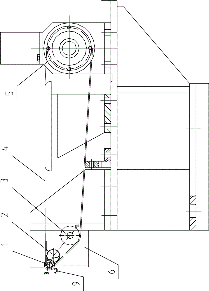
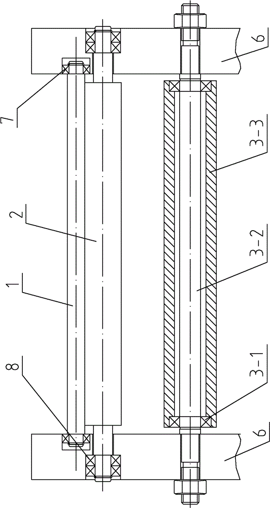
[0024] see Figure 1 ~ Figure 2 , a flux-cored wire belt-type powder feeder, comprising a powder feeding belt 4, a front shaft 1, and a rear shaft 5, the powder feeding belt 4 is tensioned on the front shaft 1 and the rear shaft 5, and the front shaft 1 is installed on the front shaft bracket 6, the powder feeding belt 4 bypasses the front shaft 1 and is frictionally connected with it. Behind the front shaft 1, there is also a support shaft 2 parallel to it. The support shaft 2 is frictionally connected with the front shaft 1, and the support shaft 2 is installed on On the front axle bracket 6. With the above structure, the diameter of the front shaft 1 can be reduced to 10 mm, or even 6 mm, without affecting the tension of the powder feeding belt 4 .

[0025] The two ends of the front axle 1 are respectively provided with first bearings 7, and the first bearings 7 at both ends of the front axle 1 are respectively embedded in mutually parallel slide grooves provided on the fr...

Embodiment 2

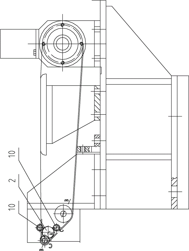
[0029] see Figure 3 ~ Figure 4 , a flux-cored wire belt-type powder feeder, the difference from Embodiment 1 is that the third bearing 11 installed at both ends of the support shaft 2 is fixed by the first screws 10 distributed in its circumferential direction, and the first screws 10 are fixed On the front axle bracket 6. The rest of the structure of the flux-cored wire belt-type powder feeder described in this embodiment is the same as that in Embodiment 1, and will not be repeated here.

Embodiment 3

[0031] see Figure 5 ~ Figure 7 , a flux-cored wire belt-type powder feeder, the difference from Embodiment 1 is that no bearings are installed at both ends of the support shaft 2, and are directly supported by two fourth bearings 12 distributed in the circumferential direction of the end of the support shaft, and the fourth Bearing 12 is installed on the second screw 13 that is affixed with front axle support 6. The two fourth bearings form a second angle with the line connecting the center of the support shaft respectively, the extension line of the line connecting the center of the front axle and the center of the support shaft is located in the range of the second angle, the support shaft 2 is frictionally connected with the fourth bearing 12, and the fourth bearing 12 is installed on the second screw 13 that is affixed with front axle bracket 6. With the above structure, the diameter of the front shaft 1 can be reduced to 4 mm, or even less than 4 mm, without affecting t...


PUM


Abstract

The invention discloses a flux-cored wire belt type powder feeder. The flux-cored wire belt type powder feeder comprises a powder feeding belt, a front shaft and a back shaft, wherein the powder feeding belt is tensioned on the front shaft and the back shaft; the front shaft is arranged on a front shaft bracket; a bearing shaft parallel to the front shaft is borne behind the front shaft; the bearing shaft is in frictional connection with the front shaft; the bearing shaft is arranged on the front shaft bracket; a first bearing is arranged at the two ends of the front shaft respectively; and the first bearings at the two ends of the front shaft are embedded into parallel chutes formed on the front shaft bracket respectively. The flux-cored wire belt type powder feeder reduces the probability that medicinal powder is attached to the belt, reduces the spatter of dust, reduces the production cost and the influence of spontaneous, random and uncontrollable procedures on the stability of a filling rate in the powder feeding process, improves the product quality and the working environment and guarantees the body health of workers.

Description

technical field [0001] The invention relates to a flux-cored wire production equipment, in particular to a flux-cored wire belt-type powder feeder. Background technique [0002] At present, the powder feeding system of the flux-cored welding wire forming machine generally adopts a belt-type powder feeder, such as the patent document CN201543973U, the wire rolling machine powder feeder disclosed on August 11, 2010. In front of the belt, it makes centripetal movement around the center of the front axis of the powder feeder. When the adsorption force between the powder and the belt is not enough to provide centripetal force, the powder will be thrown out, leave the surface of the belt, and fall into the U-shaped groove of the steel belt. . The diameter of the front shaft of the existing domestic powder feeder is generally 15-25mm. Considering the thickness of the belt is 1.8-2.5mm, the actual radius of curvature of the belt at the front shaft is 10-15mm. At this time, the radi...

Claims


Application Information

Patent Timeline
Patent Type & Authority Patents(China)
IPC IPC(8): B65G23/04B65G15/60B65G39/02
Inventor 张国良李也庚薛爱云
Owner TIANJIN SAINTEAGLE WELDING CO LTD
Why Eureka
Try Eureka