Yarn-passing device of embroidery machine

An embroidery machine and thread passing technology, which is applied to embroidery machines, embroidery machine mechanisms, textiles and paper making, etc., can solve the problems of insufficient safety, increased workload, and cumbersome threading, so as to improve production effects, reduce workload, Simple effect of threading process

Inactive Publication Date: 2011-08-03
DONGYANG JIALUN ELECTRONICS MACHINERY
View PDF10 Cites 9 Cited by
  • Summary
  • Abstract
  • Description
  • Claims
  • Application Information

AI Technical Summary

Problems solved by technology

[0005] With the development of embroidery machines, the number of heads and needles has increased greatly. The number of heads can reach 64, and the number of needles can reach 12 needles. Threading is very cumbersome
The anti-slip sheet 104 is easy to wear when the tension adjustment handle 103 is continuously adjusted, and it cannot fix the thread take-up spring 105. When using this kind of intermediate thread, it can only be equipped with a flat upper panel 101, resulting in most of the thread take-up lever 106. If it is exposed outside, when the thread take-up lever 106 moves up and down, it is easy to cause inj

Method used


Image

  • Yarn-passing device of embroidery machine
  • Yarn-passing device of embroidery machine
  • Yarn-passing device of embroidery machine

Examples


Embodiment 1

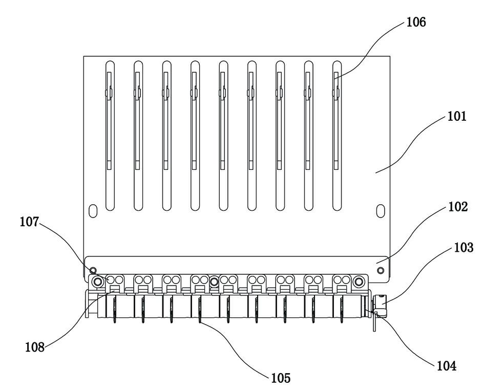
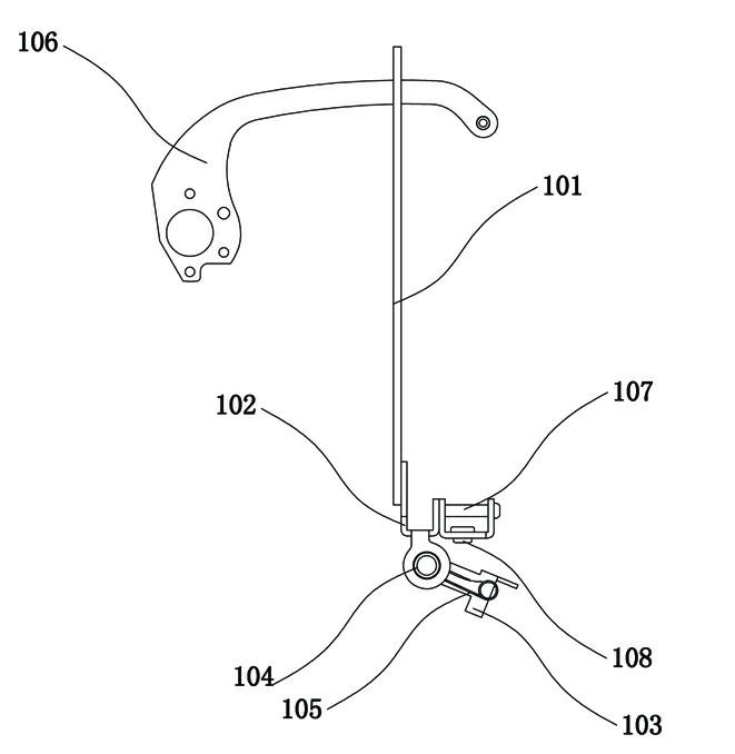
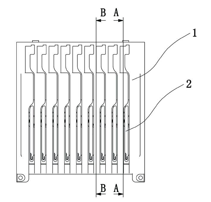
[0028] Embodiment 1: as image 3 , Figure 4 and Figure 6 As shown, a thread passing device in an embroidery machine includes a base 1. The base 1 is composed of a bottom plate and a panel. The middle part of the panel bulges outwards and its two ends are fixedly mounted on the bottom plate. A hollow cavity is formed between the two. , the cavity contains multiple sets of wire passing components. A fixed plate 9 and a line retaining plate 10 are installed on the inner surface of the base plate, and the line retaining plate 10 is installed between the base plate and the fixed plate 9 .

[0029] Such as Figure 4 and Figure 5 As shown, the wire passing assembly includes a holding plate 3 vertically installed on the fixing plate. The front end of the holding plate 3 is covered with a holding plate cover 2. The holding plate cover 2 extends out of the cavity from the panel and passes through the holding plate cover 2 of the panel. Thread grooves are reserved on both sides, ...


PUM


Abstract

The invention discloses a yarn-passing device of an embroidery machine, which comprises a base, wherein the base comprises a bottom plate and a face plate, the middle of the face plate is bulged outwards, both sides of the face plate are connected to the bottom plate, and a hollow cavity is formed between the face plate and the bottom plate; a plurality of yarn-passing assemblies are arranged in the cavity and respectively comprises a holding plate arranged on the bottom plate, the front sides of the holding plates extend out of the cavity from the face plates, and both sides of the holding plates, passing through the face plates, are provided with yarn-passing slots; and a tension regulator is arranged on one of the side face of the holding plates, and a take-up spring is arranged on thetension regulator and is provided with a tension spring end sleeved on the tension regulator and a take-up hook end extending out of the tension regulator. The whole yarn-passing device is a claddingbody; all assemblies are covered in the base so that the operators can not touch the moving parts of the yarn-passing device, thereby not resulting in part damages and personnel injuries.

Description

[0001] technical field [0002] The invention relates to the technical field of thread passing devices for embroidery machines, in particular to a thread passing device for embroidery machines. Background technique [0003] The more advanced intermediate thread of the existing embroidery machine, such as figure 1 and figure 2 As shown, this structure is also used in Chinese patent ZL200710070827, which mainly includes upper panel 101, U-shaped seat 102, tension adjustment handle 103, anti-slip sheet 104, thread take-up spring 105, thread take-up lever 106, roller 107 And over-the-line ceramic 108. [0004] Embroidery thread passes in the hole under two rollers 107, then passes in the thread take-up spring 105, then returns in the hole under the roller 107 and goes out, penetrates the thread take-up lever 106, and then passes thread ceramics 108. U-shaped seat 102 is fixed on the upper panel 101, and tension adjustment handle 103 adjusts thread take-up spring 105 to mov...

Claims


Application Information

Patent Timeline
IPC IPC(8): D05C11/10
Inventor 蒋庆丰吴高阳邵金鹏胡志清赵洪海胡鸳鸳
Owner DONGYANG JIALUN ELECTRONICS MACHINERY
Why Eureka
Try Eureka