

Roll-over safety valve
A safety valve and valve seat technology, applied in the field of rollover safety valve, can solve problems such as increased fuel leakage from orifice
- Summary
- Abstract
- Description
- Claims
- Application Information
AI Technical Summary
Problems solved by technology
Method used
Image

Examples
no. 1 approach
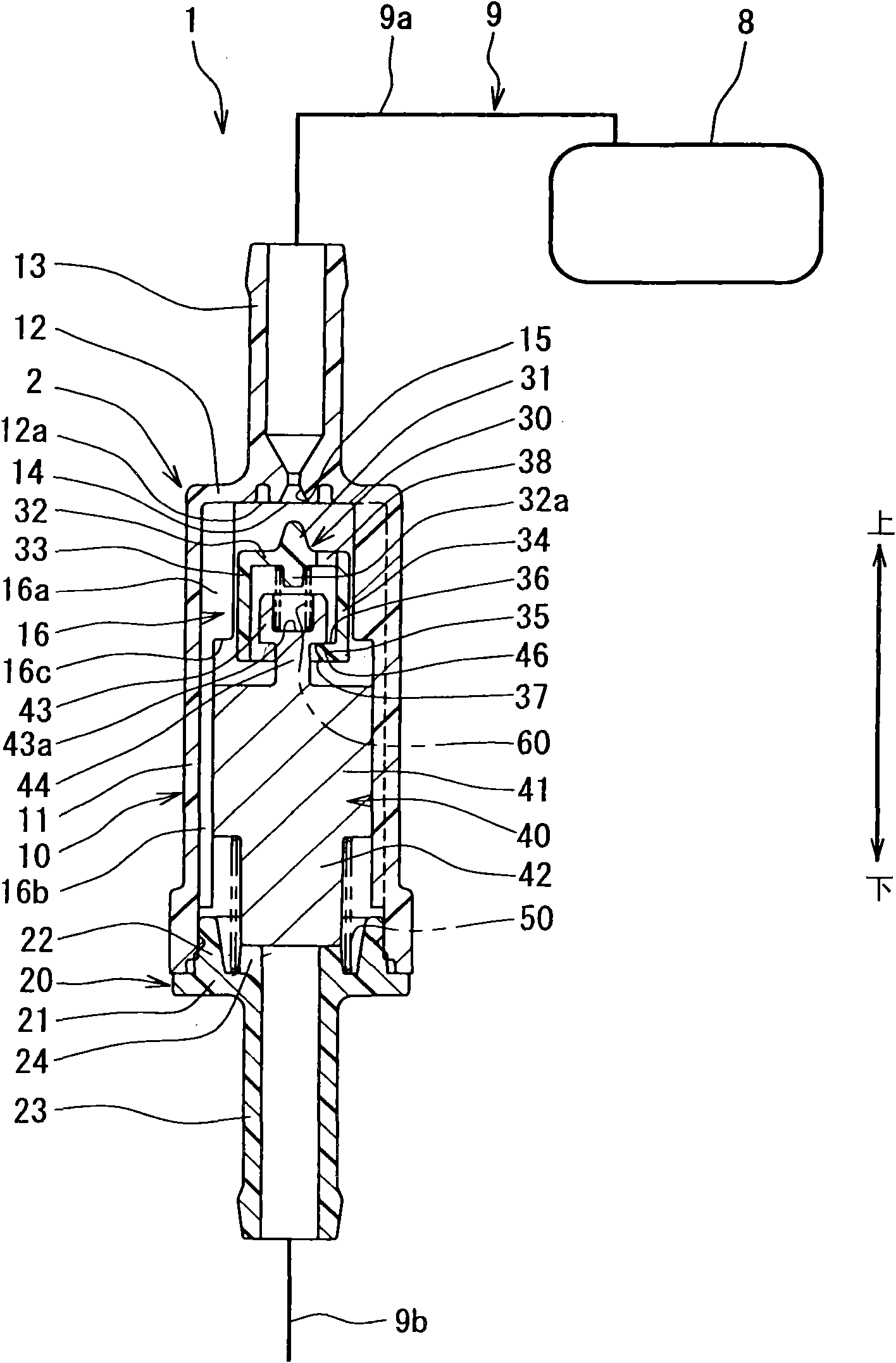
[0034] will refer to figure 1 The rollover valve 1 of the first embodiment will be described.
[0035] The rollover valve 1 is mounted on a motor vehicle such as a motorcycle, and is positioned outside a fuel tank 8 of the motor vehicle. Such as figure 1 As shown, a drain passage extends from the fuel tank 8 through which vaporized fuel is released from the fuel tank 8 . The rollover valve 1 is disposed in the discharge passage, and the longitudinal direction of the rollover valve 1 corresponds to the up-down direction of the motor vehicle.
[0036]The rollover valve 1 has a valve element 30 , a weight portion 40 , a first spring 50 and a second spring 60 which are arranged in the housing 2 of the rollover valve 1 . The housing 2 is made of resin, for example, and has a valve body 10 and a valve cover 20 . The valve body 10 has a cylindrical portion 11 extending in an up-down direction, and a valve cover 20 is fixed to the lower opening of the cylindrical portion 11 .
[...
no. 2 approach
[0075] will refer to image 3 , 4A and 4B describe the second embodiment.
[0076] The rollover valve 1 of the second embodiment has a valve element 130 and a weight portion 140 respectively different from the valve element 30 and the weight portion 40 of the first embodiment. The same parts as in the first embodiment have the same reference numerals as in the first embodiment, and descriptions of the same parts are omitted.
[0077] will refer to image 3 The rollover valve 1 of the second embodiment will be described.
[0078] Such as image 3 As shown, the valve member 130 is made of resin, for example, and has a disc portion 32, a cylindrical portion 33, a needle 31 and a flange 135, which are integrally molded. The disk portion 32 is circumferentially expanded in a direction perpendicular to the axial direction of the cylindrical portion 11 . The cylindrical portion 33 extends downward from the outer peripheral area of the disc portion 32 . The needle 31 protrude...
no. 3 approach
[0104] will refer to Figure 5 , 6A and 6B describe the third embodiment.
[0105] The rollover valve 1 of the third embodiment has a valve element 230, a weight portion 240, and a spring 250 respectively different from the valve element 30, the weight portion 40, and the spring 50 of the first embodiment. The same parts as in the above-mentioned embodiment have the same reference numerals as in the above-mentioned embodiment, and descriptions of the same parts are omitted.
[0106] will refer to Figure 5 The rollover valve 1 of the third embodiment will be described.
[0107] Such as Figure 5As shown, the valve member 230 is made of, for example, resin, and has a post portion 232, a needle 31, a flange 235, and a protrusion portion 239, which are integrally molded, wherein the post portion 232 extends in the axial direction. The needle 31 protrudes upward from the central region of the upper end portion of the pier portion 232 . The flange 135 protrudes radially and c...
PUM
 Abstract
Description
Claims
Application Information