Apparatus for detecting particles on a flat glass

A flat glass and foreign matter detection technology, applied in the direction of measuring devices, material analysis through optical means, instruments, etc., can solve the problems of inability to detect, inaccurate detection results, and inability to obtain accurate information, etc., and achieve the effect of reducing adverse phenomena

Inactive Publication Date: 2011-08-03
SAMSUNG CORNING PRECISION MATERIALS CO LTD
View PDF5 Cites 25 Cited by
  • Summary
  • Abstract
  • Description
  • Claims
  • Application Information

AI Technical Summary

Problems solved by technology

However, figure 1 There is the following problem in the existing foreign matter detection device on the surface of flat glass: if the thickness of the laser beam used is not very thin, it is impossible to detect only the foreign matter on the A side of the flat glass. The thickness of the beam, a part of the foreign matter 91 existing on the B side of the flat glass will also be detected
[0007] Since it is a common phenomenon that foreign matter adheres to the A side of the flat glass and the B side of the flat glass, figure 1 As shown in the existing foreign object detection device, a part of the foreign matter located on the B side of the flat glass is detected, so if the detection result is used, it is impossible to obtain accurate information about the foreign matter on the A side of the flat glass
In addition, in the current situation, as the thickness of the plate glass becomes thinner, the difference in the horizontal distance between the portion where the incident laser beam 31 reaches the A surface of the plate glass and the portion where the projected laser beam 35 reaches the B surface of the plate glass is δL is reduced, so the detection results are less accurate
[0008] Another problem is that when the transfer device of the flat glass vibrates up and down, it will become more difficult to accurately distinguish the foreign matter on the A side from the foreign matter on the B side
Therefore, there is a problem that, in order to solve the above-mentioned problems, it is necessary to use expensive precision conveying equipment in the existing flat glass foreign matter detection device.

Method used


Image

  • Apparatus for detecting particles on a flat glass
  • Apparatus for detecting particles on a flat glass
  • Apparatus for detecting particles on a flat glass

Examples


Embodiment Construction

[0061] Hereinafter, preferred embodiments of the foreign matter detection device on a plate glass surface according to the present invention will be described in detail with reference to the drawings.

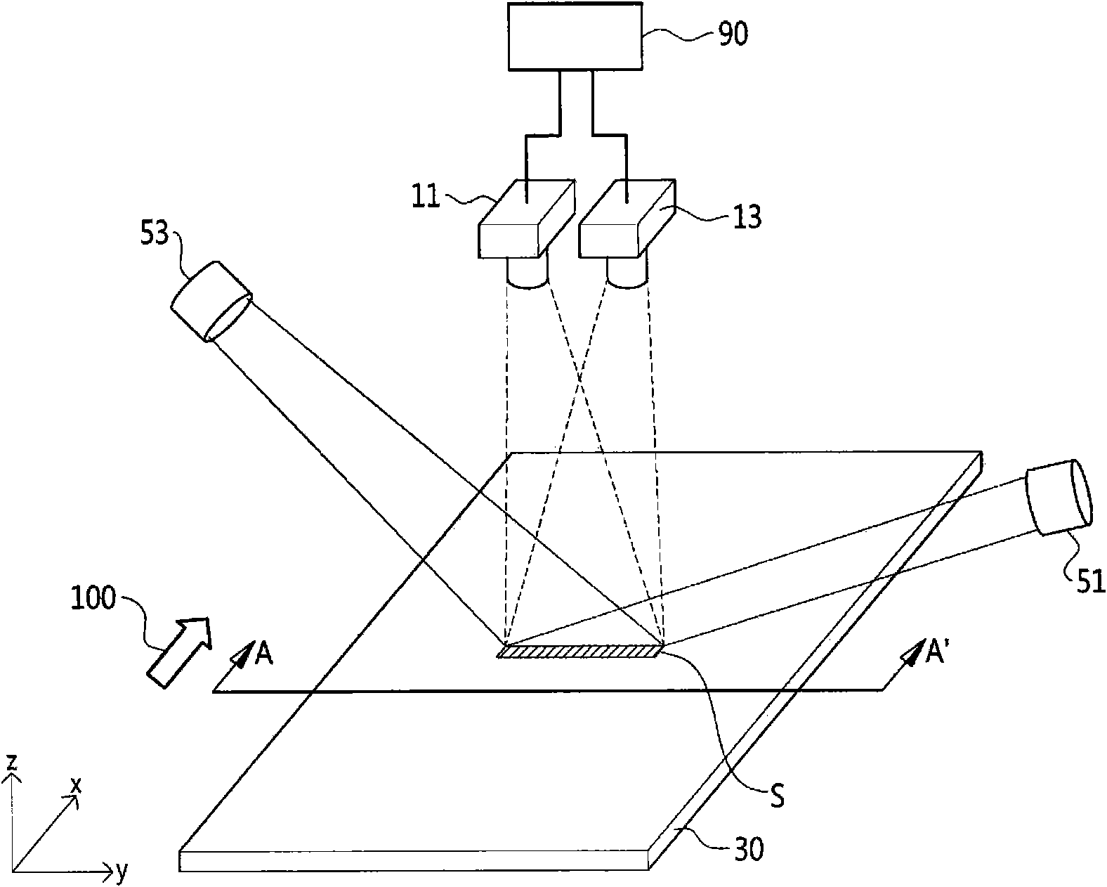
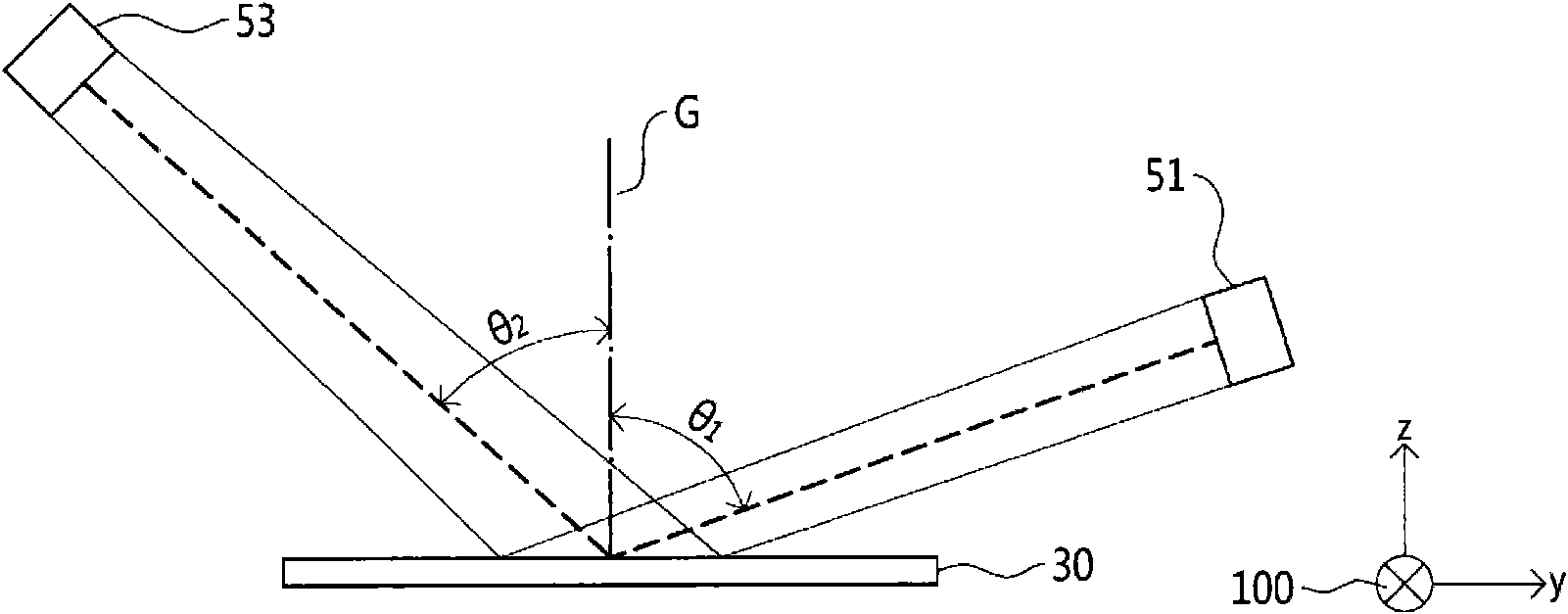
[0062] figure 2 It is a structural diagram schematically showing a preferred embodiment of the foreign matter detection device on the surface of flat glass of the present invention, image 3 yes figure 2 A partial cross-sectional view of the A-A' direction.

[0063] Before the description, one side where the A-side laser beam irradiating device 51 and the B-side laser beam irradiating device 53 are respectively provided is defined as the following meaning: among the four corners of the flat glass substrate 30 formed into a rectangle, the A corner portion at a position parallel to the transfer direction of the glass substrate 30 .

[0064] refer to figure 2 and image 3 , the foreign matter detection device on the flat glass surface of the present invention includes: A-s...


PUM


Abstract

The present invention relates to an apparatus for detecting particles on a flat glass, comprising: a surface A laser light irradiating device for irradiating laser light of a first wavelength polarized in a direction S at a first angle based on a surface A normal vector toward the surface A in an upper part of the surface A of the flat glass; a surface A photographing device for taking a picture of a point where the laser light irradiated by the surface A laser light irradiating device is irradiated on the surface A of the flat glass; a surface B laser light irradiating device for irradiating laser light of a second wavelength toward the surface A at a second angle smaller than the first angle based on the surface A normal vector in the upper part of the surface A of the flat glass, and wherein the irradiated laser light is mostly transmitted in thickness direction of the flat glass; a surface B photographing device for taking a picture of a point where the laser light irradiated by the surface B laser light irradiating device is irradiated on the surface B of the flat glass; and a detection signal processor.

Description

technical field [0001] The present invention relates to a foreign matter detection device on the surface of a flat glass plate, and more specifically, to a flat glass capable of accurately detecting foreign matter on a surface on which a micro-circuit pattern is vapor-deposited Surface foreign object detection device. Background technique [0002] The flat glass used for flat panel display (plat display) has microcircuit patterns evaporated on one side only. The glass industry calls this side "A side", while the other side is not evaporated with microcircuit patterns. And the glass industry calls this other side "B side". [0003] When there is a foreign matter on the surface of the A side of the plate glass, if the pattern of the microcircuit is vapor-deposited on the foreign matter, the pattern defect of the microcircuit is likely to occur. Therefore, before evaporating the pattern of the microcircuit, it is necessary to accurately check whether there are foreign objects...

Claims


Application Information

Patent Timeline
Patent Type & Authority Applications(China)
IPC IPC(8): G01N21/956
CPCH04N7/18G01N21/01G01N21/956G01N2021/0106G01N2021/9513G01N21/958G01N21/94G01N21/21G01N21/896
Inventor 金贤祐朴晋弘金台皓李昌夏
Owner SAMSUNG CORNING PRECISION MATERIALS CO LTD
Why Eureka
Try Eureka