

Cathode-ray tube having oxide cathode and method for producing same
An oxide cathode, cathode ray tube technology, applied in cathode ray tube/electron beam tube, cold cathode manufacturing, thermionic cathode manufacturing, etc., can solve problems such as low electron emission
- Summary
- Abstract
- Description
- Claims
- Application Information
AI Technical Summary
Problems solved by technology
Method used
Image

Examples
Embodiment 1
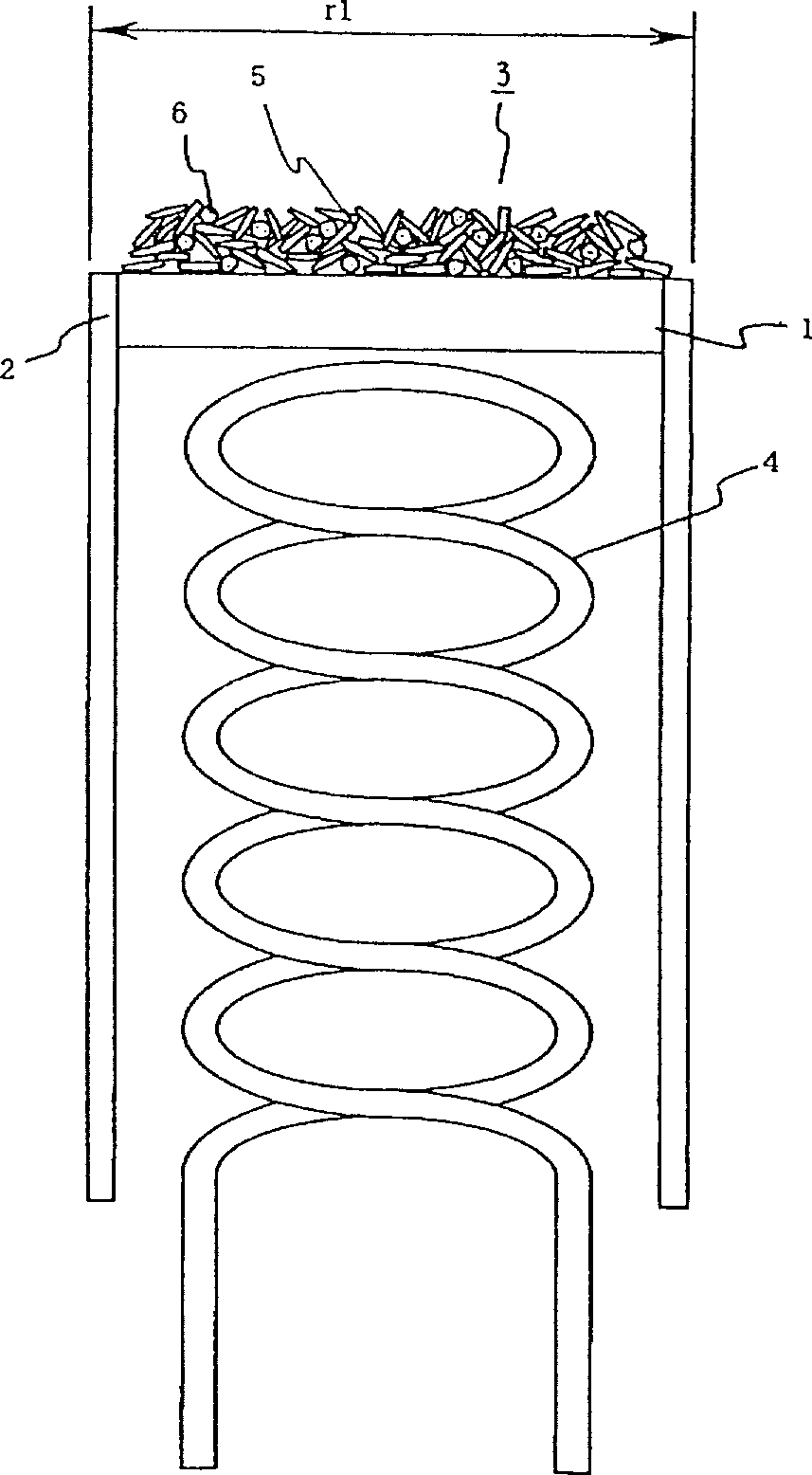
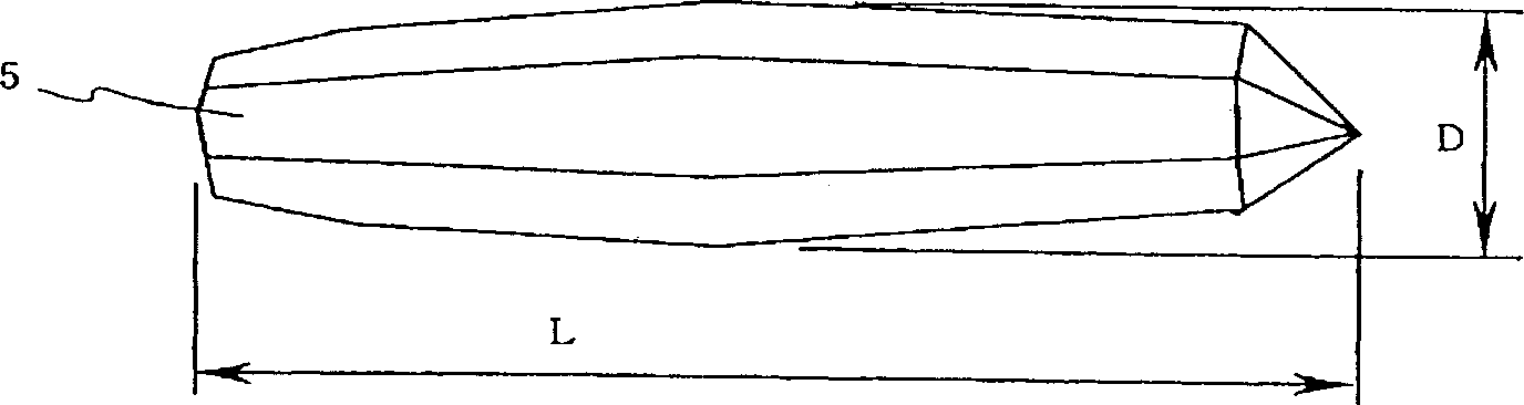
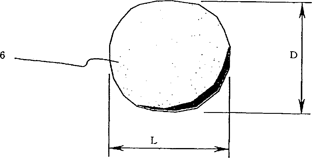
[0045] Hereinafter, embodiments of the present invention will be described with reference to the drawings. figure 1 It is an enlarged cross-sectional view of the oxide cathode part of the cathode ray tube of Embodiment 1 of the present invention, 1 is a disc-shaped metal substrate, 2 is a sleeve supporting the metal substrate, and 3 is coated on the metal substrate 1 The electron-emitting material layer mainly composed of alkaline earth oxide particles, 4 is an incandescent wire for heating the electron-emitting material layer, and the oxide cathode is set in a cathode ray tube (not shown in the figure) that maintains vacuum . The particles of the alkaline earth metal oxide forming the electron emissive material layer are composed of needle-like first-type particles 5 and approximately spherical second-type particles 6 . The first type of particles is more than the second type of particles, the average length L of the first type of particles is longer than that of the second...
Embodiment 2
[0069] Hereinafter, another embodiment of the present invention will be described with reference to the drawings. Figure 6 It is an enlarged cross-sectional view of a part of an oxide cathode of a cathode ray tube according to Example 2 of the present invention, Figure 7 is for manufacturing Figure 6 The cathode ray tube shown is a cross-sectional view of the same position after applying printing paste to be an electron emissive material layer by screen printing and drying it. Such as Figure 7 As shown, layer 3 serving as the electron emissive material layer is mainly composed of carbonate particles 5 which are alkaline earth metals, and porous material particles 7 . After making a cathode ray tube, such as Figure 6 As shown, the porous material particle 7 decomposes and evaporates without remaining, but the position where the porous material particle is located becomes a void. That is, suitable voids, especially pores, are formed on the surface. Therefore, it is pos...
Embodiment 3
[0083] Figure 8 It is an enlarged cross-sectional view of a part of the oxide cathode of the cathode ray tube according to Example 3 of the present invention, Figure 9 is for manufacturing Figure 8 The cathode ray tube shown is a cross-sectional view of the same position after the printing paste used as the electron emissive material layer is applied by the screen printing method and dried. Such as Figure 9 As shown, the layer 3 serving as the electron emissive material layer is mainly composed of carbonate particles 5 and 6 which are alkaline earth metals, and porous material particles 7 . Among them, the alkaline earth metal carbonate is composed of normal needle-shaped particles as the first group of particles 5 , and the second group of particles having a smaller average length L and a larger average diameter D than the first group of particles. This embodiment is equivalent to adding void material particles when manufacturing the cathode ray tube of the first embod...
PUM
| Property | Measurement | Unit |
|---|---|---|
| The average diameter | aaaaa | aaaaa |
| Diameter | aaaaa | aaaaa |
| Viscosity | aaaaa | aaaaa |
Abstract
Description
Claims
Application Information