
Low-erosion internal ion source for cyclotrons

Active Publication Date: 2022-11-08
CENT DE INVESTIGACIONES ENERGETICAS MEDIO AMBIENTALLES Y TECNOLOGICAS (C I E M A T)
View PDF51 Cites 0 Cited by
  • Summary
  • Abstract
  • Description
  • Claims
  • Application Information

AI Technical Summary

Benefits of technology

The present invention is an ion source that has a resonator or coaxial resonant chamber, which increases the electric field and facilitates ignition, resulting in lower energy consumption. The ion source achieves this without the need for hot cathodes at temperatures of the order of 2000 K, which means that less expensive materials such as copper can be used instead of tantalum. The invention also reduces the heating of the cathodes, leading to lower temperatures and improved performance. Overall, this invention provides a more efficient and effective ion source for various applications.

Problems solved by technology

The drawback of these sources is erosion on the cathode due to the high potential difference of the cathode, necessary for accelerating the electrons, which causes the ions to be accelerated in the opposite direction and impact against the cathode, removing material (sputtering) and limiting the life of said cathode.Radio-frequency discharge: they are an evolution of DC sources because they use an alternating electric field to accelerate the electrons instead of a continuous one.
Penning ion sources have the drawback of the sputtering of cathodes which, despite being commonly made of materials with high resistance and high electron emission (such as tantalum), are subjected to excessive wear that makes frequent replacement necessary.
The use of an external source adds greater complexity to the system although it allows other methods to be used to generate the plasma, such that manufacturers do not usually include them in their commercial cyclotrons.
The problem with all sources that use DC discharges is that this type of discharge erodes the cathodes while the plasma is active, meaning that they must be changed periodically and in these machines that are used for medical applications, it is generally desirable to have it running for as long as possible without interruptions.

Method used


Image

  • Low-erosion internal ion source for cyclotrons
  • Low-erosion internal ion source for cyclotrons
  • Low-erosion internal ion source for cyclotrons

Examples


Embodiment Construction

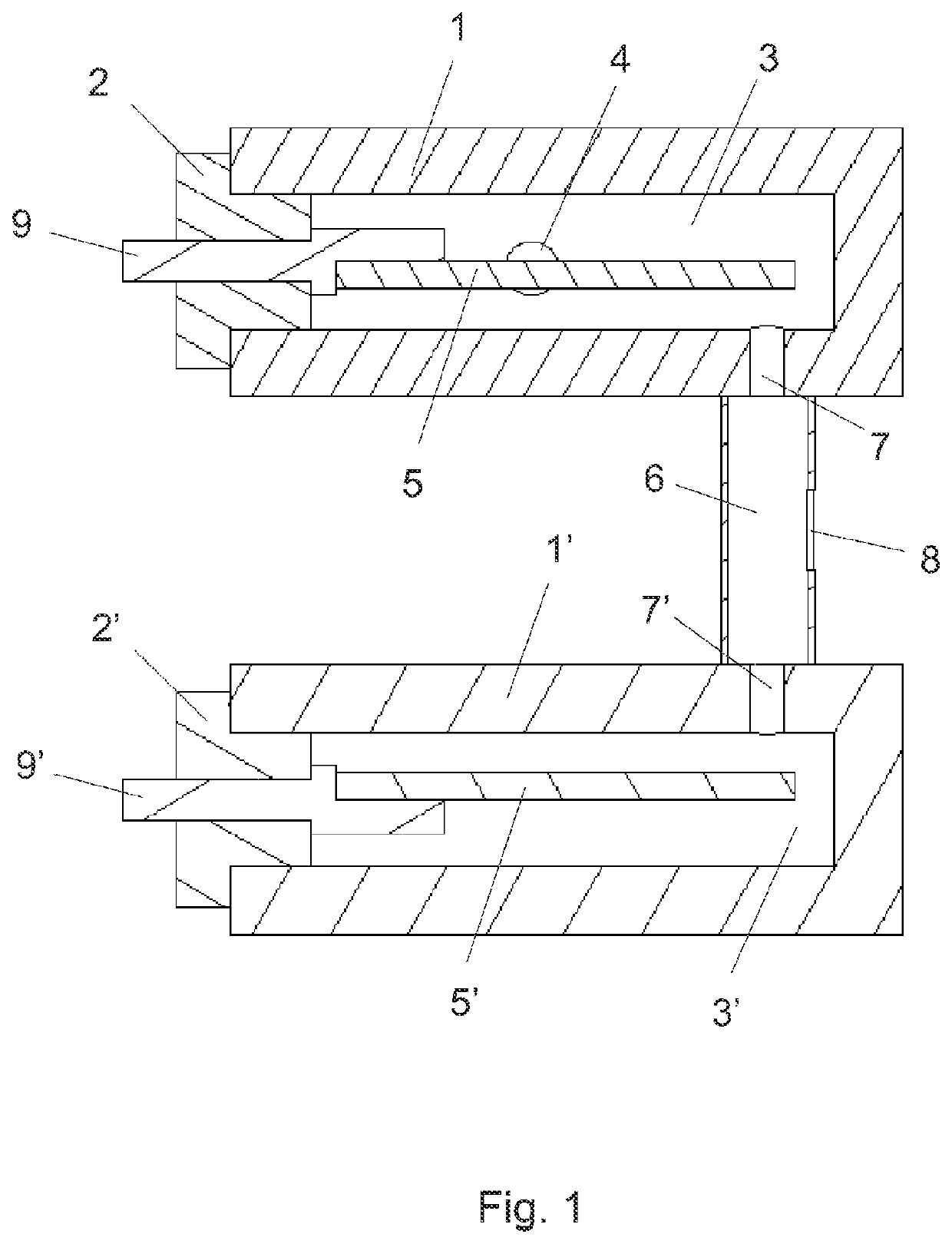
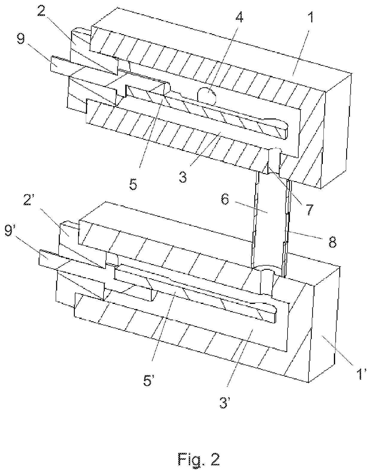
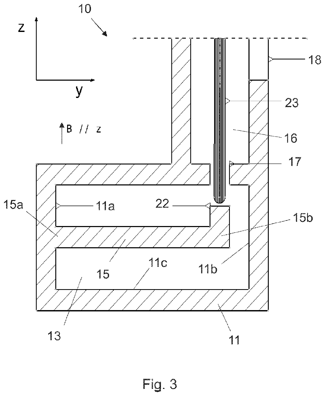
[0016]The present invention relates to a low-erosion radio frequency ion source, especially useful for use as an internal ion source for cyclotrons.

[0017]The ion source comprises:[0018]A hollow body whose interior walls define a cylindrical cavity. The body has a gas supply inlet through which a plasma-forming gas is introduced into the cavity. The body has a power supply inlet through which radio frequency energy is injected into the cavity. The interior walls of the body are electrically conductive (preferably the entire body is conductive).[0019]An expansion chamber connected to the cavity through a plasma outlet hole made in the body.[0020]An ion-extraction aperture in contact with the expansion chamber.[0021]A coaxial conductor disposed in the cavity of the body, arranged parallel to the longitudinal axis of the cavity. At least one of the ends of the coaxial conductor is in contact with at least one circular interior wall of the body, forming a coaxial resonant cavity. The coa...


PUM


Abstract

A low-erosion radio frequency ion source is disclosed having a hollow body with conductive interior walls that define a cylindrical cavity, with a gas supply inlet for plasma-forming gases and a power supply inlet for injecting radio frequency energy into the cavity; an expansion chamber connected to the cavity by means of a plasma outlet hole; an ion-extraction aperture in contact with the expansion chamber; coaxial conductor disposed in the cavity, parallel to the longitudinal axis thereof, one or both ends of the coaxial conductor being in contact with a circular interior wall of the body, forming a coaxial resonant cavity; the coaxial conductor having a conductive protuberance opposite the plasma outlet hole and which extends radially into the cavity. It substantially reduces the erosion of the conductive materials.

Description

CROSS REFERENCE TO RELATED APPLICATION[0001]This Application is a 371 of PCT / ES2019 / 070461 filed on Jul. 1, 2019 which, in turn, claimed the priority of Spanish Patent Application No. P201830684 filed on Jul. 10, 2018, both applications are incorporated herein by reference.FIELD OF THE INVENTION[0002]The present invention falls within the field of ion sources for particle accelerators.BACKGROUND OF THE INVENTION[0003]An ion source is the component of particle accelerators where the gas is ionised, transforming into plasma, and from which the charged particles are then extracted to be accelerated. Ion sources are mainly used as internal sources in cyclotrons to produce lightweight positive ions and negative hydrogen. These types of machines have been traditionally used in the world of research as multipurpose beam machines for use in multiple fields. They have recently been used for radioisotope synthesis in radiopharmaceutical applications, as well as in proton / hadron therapy machin...

Claims


Application Information

Patent Timeline
Patent Type & Authority Patents(United States)
IPC IPC(8): H05H7/18H05H7/08H05H13/00
CPCH05H7/18H05H7/08H05H13/005H05H2007/082H01J27/18
Inventor VARELA ALONSO, RODRIGO
Owner CENT DE INVESTIGACIONES ENERGETICAS MEDIO AMBIENTALLES Y TECNOLOGICAS (C I E M A T)
Learn More