Optical thin film and backlight unit

A technology of optical film and optical film, which is applied in the field of optics, can solve problems such as the influence of light transmission, poor shielding performance of optical film structure, and reduce the light transmission efficiency in the backlight unit, so as to achieve the effect of reducing molar interference and good shielding performance

Active Publication Date: 2015-09-30
ZHANGJIAGANG KANGDE XIN OPTRONICS MATERIAL
View PDF10 Cites 4 Cited by
  • Summary
  • Abstract
  • Description
  • Claims
  • Application Information

AI Technical Summary

Problems solved by technology

[0004] However, due to the barriers provided in the optical film structure in the prior art, it will affect the light transmission in the entire optical film, thereby reducing the light transmission efficiency in the backlight unit, and the limitation of the material of the barriers will also cause the optical film The structure is poorly shielded

Method used


Image

  • Optical thin film and backlight unit
  • Optical thin film and backlight unit
  • Optical thin film and backlight unit

Examples


Embodiment 1

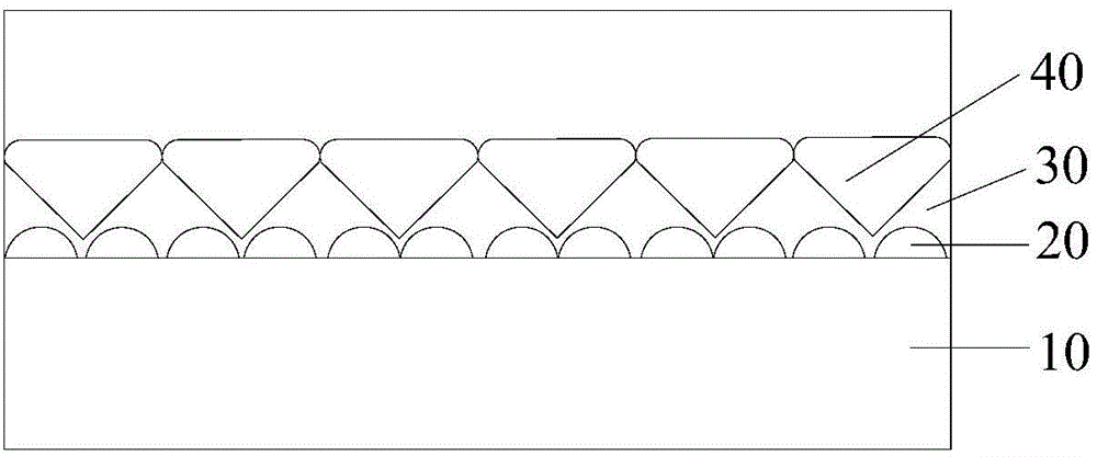
[0046] The optical film provided by this embodiment is as figure 1 As shown, the optical film includes two layers of transparent material layers stacked, and the materials of the two transparent material layers are both acrylic acid copolymers;

[0047] And a first raised structure and a second raised structure covered on the first raised structure are arranged between the two transparent material layers, and the first raised structure includes a plurality of first raised parts sequentially arranged along the direction a , the second protrusion structure includes a plurality of second protrusions arranged in sequence along the a direction, the first protrusions and the second protrusions both penetrate the transparent material layer along the b direction, the a direction is perpendicular to the b direction, and the a direction The directions b and b are parallel to the extended surface of the transparent material layer, each second raised portion covers at least one first rais...

Embodiment 2

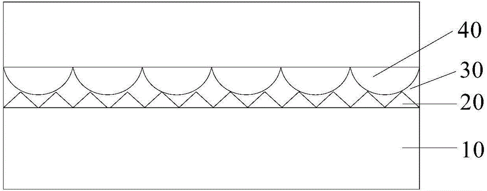
[0051] The optical film provided by this embodiment is as figure 2 As shown, the optical film includes two layers of transparent material layers stacked, and the materials of the two layers of transparent material layers are both ethylene copolymers;

[0052] And a first raised structure and a second raised structure covered on the first raised structure are arranged between the two transparent material layers, and the first raised structure includes a plurality of first raised parts sequentially arranged along the direction a , the second protrusion structure includes a plurality of second protrusions arranged in sequence along the a direction, the first protrusions and the second protrusions both penetrate the transparent material layer along the b direction, the a direction is perpendicular to the b direction, and the a direction The directions b and b are parallel to the extended surface of the transparent material layer, each second raised portion covers at least one fir...

Embodiment 3

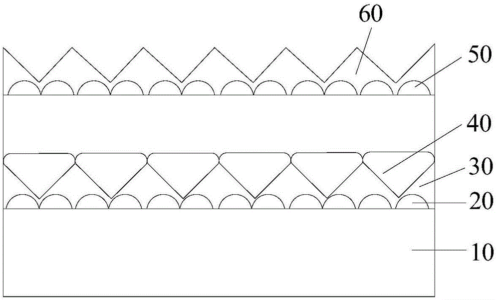
[0056] The optical film provided by this embodiment is as image 3 As shown, the optical film includes two layers of transparent material layers stacked, and the materials of the two transparent material layers are both acrylic acid copolymers;

[0057] And a first raised structure and a second raised structure covered on the first raised structure are arranged between the two transparent material layers, and the first raised structure includes a plurality of first raised parts sequentially arranged along the direction a , the second protrusion structure includes a plurality of second protrusions arranged in sequence along the a direction, the first protrusions and the second protrusions both penetrate the transparent material layer along the b direction, the a direction is perpendicular to the b direction, and the a direction The directions b and b are parallel to the extended surface of the transparent material layer, each second raised portion covers at least one first raised...


PUM


Abstract

The invention provides an optical thin film and a backlight unit. The optical thin film comprises a plurality of stacked transparent material layers, wherein a first composite structure layer is arranged between at least two adjacent transparent material layers and comprises a first bulge structure and a second bulge structure covering the first bulge structure, the first bulge structure comprises a plurality of first bulge parts sequentially arranged in the a direction, the second bulge structure comprises a plurality of second bulge parts sequentially arranged in the a direction, the first bulge parts and the second bulge parts penetrate through the transparent material layers in the b direction, the a direction and the b direction are perpendicular to each other and are parallel to the extending surface of each transparent material layer, each second bulge part covers at least one first bulge part, an air channel is formed by a gap between every two adjacent second bulge parts, and the first bulge structure and the second bulge structure have different refractive indexes. The optical thin film has good shielding performance, and the probability of occurrence of phenomena of moire interference, newton ring and the like is lower.

Description

technical field [0001] The invention relates to the field of optical technology, in particular to an optical film and a backlight unit. Background technique [0002] With the development of the information age, flat panel displays such as active matrix liquid crystal displays (LCDs), plasma display panels (PDPs), electroluminescence displays (ELs), and field emission displays (FEDs) have appeared, which The display has excellent properties such as thin profile, light weight and low power consumption. Among them, LCDs are widely used in notebook computers, monitors, TVs, etc. instead of cathode ray tubes (CRTs) due to their high contrast ratio and characteristics suitable for displaying moving images. [0003] A light source is not included in the LCD, so an additional light source is required. For example, a backlight unit including a light source is disposed under the liquid crystal panel to provide light to the liquid crystal panel so that the LCD can display images thro...

Claims


Application Information

Patent Timeline
Patent Type & Authority Applications(China)
IPC IPC(8): G02B5/04G02B5/02
Inventor 金星南其他发明人请求不公开姓名
Owner ZHANGJIAGANG KANGDE XIN OPTRONICS MATERIAL
Why Eureka
Try Eureka