
Direct type zero-OD backlight structure with semi-reflecting and semi-transmitting light guide plate

A semi-reflective, semi-transparent, backlight structure technology, applied in the direction of light guides, optics, optical components, etc., can solve problems such as limited use of light source luminance, inability to control light in different areas, and difficulties in optical design, so as to improve light utilization and shading Excellent performance and good effect

Active Publication Date: 2019-04-02
合肥泰沃达智能装备有限公司
View PDF6 Cites 1 Cited by
  • Summary
  • Abstract
  • Description
  • Claims
  • Application Information

AI Technical Summary

Problems solved by technology

The disadvantage is that because the light source is placed on the side of the light guide plate, the number of LEDs and the brightness are limited, and the light still needs to be evenly dispersed on the entire plane. When the panel area is larger, the brightness of the light source is more limited, and the optical design is more difficult. And the manufacturing cost is relatively high, and it is impossible to control light in different areas

Method used


Image

  • Direct type zero-OD backlight structure with semi-reflecting and semi-transmitting light guide plate

Examples


Embodiment Construction

[0023] The following will clearly and completely describe the technical solutions in the embodiments of the present invention with reference to the accompanying drawings in the embodiments of the present invention. Obviously, the described embodiments are only some, not all, embodiments of the present invention. Based on the embodiments of the present invention, all other embodiments obtained by persons of ordinary skill in the art without creative efforts fall within the protection scope of the present invention.

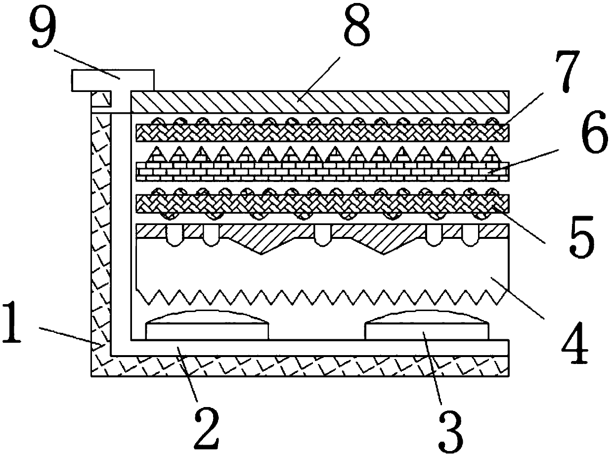
[0024] see figure 1 As shown, this embodiment provides a direct-down zero OD backlight structure with a semi-reflective and semi-transparent light guide plate, including a backplane 1, a rectangular groove is opened on the upper surface of the backplane 1, and the inner bottom wall of the rectangular groove is painted with white The reflective layer 2, the white reflective layer 2 is fixedly connected with the LED light source 3, and the back plate 1, the white ref...


PUM

PropertyMeasurementUnit
Thicknessaaaaaaaaaa
Thicknessaaaaaaaaaa

Abstract

The invention discloses a direct type zero-OD backlight structure with a semi-reflecting and semi-transmitting light guide plate. A rectangular groove is formed on the upper end face of a backplane; the inner bottom wall of the rectangular groove is coated with a white reflective layer; an LED light source is fixedly connected to the white reflective layer; the LED light source is fixedly providedwith the semi-reflecting and semi-transmitting light guide plate; a lower diffusion film is fixed to the semi-reflecting and semi-transmitting light guide plate; a prism film is fixed to the lower diffusion film; and an upper diffusion film is fixed to the prism film. According to the direct type zero-OD backlight structure with the semi-reflecting and semi-transmitting light guide plate, the semi-reflecting and semi-transmitting light guide plate is made of PS material, is lower in weight and cost; due to the improvement of the light efficiency and the haze, the films can be correspondinglyreduced, so that the cost can be further reduced; the invention has the advantages of being edge type and thin, and the total thickness is no more than 8 mm; the shielding property is excellent, and the OD approaches 0, so that the utilization rate of light can be increased, light leakage can be avoided, curved display can be achieved, and the development requirement of being thin can be met; andthe invention further has the advantage of being direct type, so that the partition dimming can be realized, and the brightness of the light emitting mode thereof is higher than the edge type.

Description

technical field [0001] The invention relates to the related technical field of backlight structures, in particular to a direct-type zero-OD backlight structure with a semi-reflective and semi-transparent light guide plate. Background technique [0002] The backlight structure is a backlight light source component in LCD display products. It generally consists of a backlight light source, multi-layer backlight materials and a support frame. The light emitted by a traditional backlight light source will only have 60% after passing through the reflective film diffusion film. When light enters the polarizing film, the light loss is high. Common structures include direct-type backlight structure and side-type backlight structure. [0003] The direct-type backlight has a simple process and does not require a light guide plate. The LED array is placed at the bottom of the light box. The light emitted from the LEDs is reflected from the bottom and sides, and then evenly emitted thr...

Claims


Application Information

Patent Timeline
IPC IPC(8): G02F1/13357G02B6/00
CPCG02B6/0025G02B6/0053G02B6/0065G02F1/133603G02F1/133605G02F1/133606G02F1/133607
Inventor 覃佐波刘莎莉
Owner 合肥泰沃达智能装备有限公司
Learn More