
Panel structure

A technology of inserts and inserts, which is applied in the manufacture of electrical components, semiconductor/solid-state devices, circuits, etc., can solve problems such as the trouble of replacing inserts, and achieve the effects of short processing cycle, reduced cost and simple processing

Inactive Publication Date: 2011-08-03
NANTONG SHANGMING PRECISION MOLD
View PDF0 Cites 0 Cited by
  • Summary
  • Abstract
  • Description
  • Claims
  • Application Information

AI Technical Summary

Problems solved by technology

It is also more troublesome to replace the inlays. You need to disassemble all the lower molds to replace the lower inlays.

Method used


Image

  • Panel structure
  • Panel structure

Examples


Embodiment

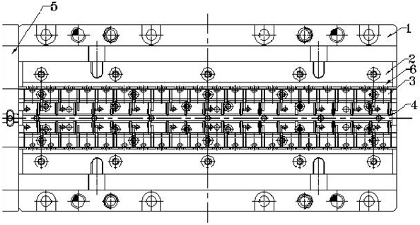
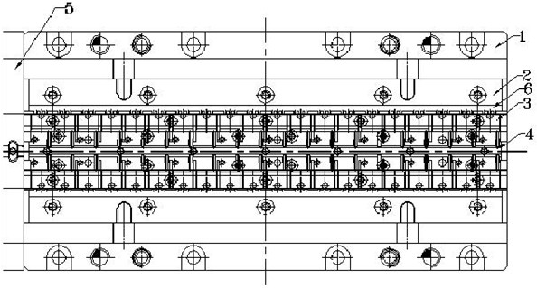
[0009] As shown in Figure 2, a molding structure provided by the present invention includes a lower mold assembly 1. In the lower mold assembly 1, a lower edge molding bar 2, a lower molding bar 3, and a runner bar 4 are sequentially provided. The plate 5 is connected to the lower mold assembly 1, and an insert 6 is assembled at the two ends of the lower insert 2 where the plastic molding compound is easily abraded.

[0010] The molding compound is injected into the cavity of the lower molding bar 3 through the sprue on the runner bar 4 through the gate. The inserts 6 at both ends of the pipe are easily worn by the molding compound and often need to be replaced. However, it is more economical to replace only one small insert 6. When replacing, just remove the lower mold closing baffle 5, and knock off the insert 6 from the side to replace it, without disassembling the entire mold. Such a mosaic method not only reduces the production cost, but is also very convenient to replace....


PUM


Abstract

The invention provides a panel structure, which comprises a lower mould closer, wherein a lower panel, a lower moulding strip and a runner strip are arranged in the lower mould closer sequentially; and a lower mould closer baffle is connected to the lower mould closer. The panel structure is characterized in that: an insert is spliced at parts which are easy to abrade by a plastic material at each end of the lower panel. In the panel structure, the parts at the two ends of the lower panel, which are easy to abrade, are made into the independent inserts, and a seam between a lower insert and the lower panel is formed in a non-moulding place between two pipes. Replacement of the inserts is convenient and economical relatively. Compared with cost for replacement of the whole panel, the cost for the replacement of only one small workpiece is reduced greatly. The inserts have the advantages of simple processing, short processing period, low processing cost and the like.

Description

Technical field [0001] The invention relates to a strip structure used in the molding part of a semiconductor packaging mold. Background technique [0002] During the semiconductor packaging process, some plastic molding compounds will have an impact on the inserts in the molded part. The current integral molding structure is composed of lower mold closure, lower edge molding, lower molding strip, runner strip, and lower mold closure baffle. Because some molding compounds contain more silicon particles, the hardness of the molding compound is relatively high, and the molding compound also has the characteristics of high fluidity. When the injection pressure of the press reaches 200 tons, the molding compound is injected into the cavity of the upper molding bar 3 through the sprue on the sprue 4 through the gate, and the molding compound is injected into the molding part of the molding under pressure. The formation of impact force will cause a certain degree of wear to the inser...

Claims


Application Information

Patent Timeline
Patent Type & Authority Applications(China)
IPC IPC(8): H01L21/56
Inventor 万礼锋
Owner NANTONG SHANGMING PRECISION MOLD
Learn More