Supercharge Your Innovation With Domain-Expert AI Agents!

GMR sensor within molded magnetic material employing non-magnetic spacer

A technology of non-magnetic materials and magnetic materials, which can be used in the selection of materials, conversion of sensor output, manufacturing/processing of electromagnetic devices, etc., and can solve problems such as the inability of sensors to work

Active Publication Date: 2011-08-03
INFINEON TECH AG
View PDF2 Cites 3 Cited by
  • Summary
  • Abstract
  • Description
  • Claims
  • Application Information

AI Technical Summary

Problems solved by technology

While this approach alleviates many of the above-mentioned problems, it was found that the ferromagnetic material of the lead frame (e.g., copper) deforms (distorts) in the magnetic field or flux lines at the XMR element, where the deformation results in a magnetic field parallel to the magnetic field sensor surface. The magnetic field level component (that is, the component being detected) has a magnitude that causes the XMR sensor to saturate, thereby rendering the sensor inoperable

Method used


Image

  • GMR sensor within molded magnetic material employing non-magnetic spacer
  • GMR sensor within molded magnetic material employing non-magnetic spacer
  • GMR sensor within molded magnetic material employing non-magnetic spacer

Examples


Embodiment Construction

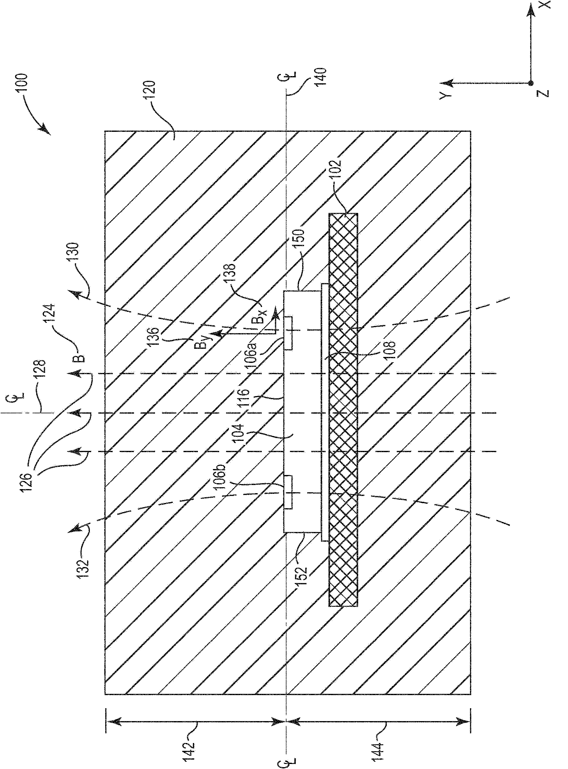
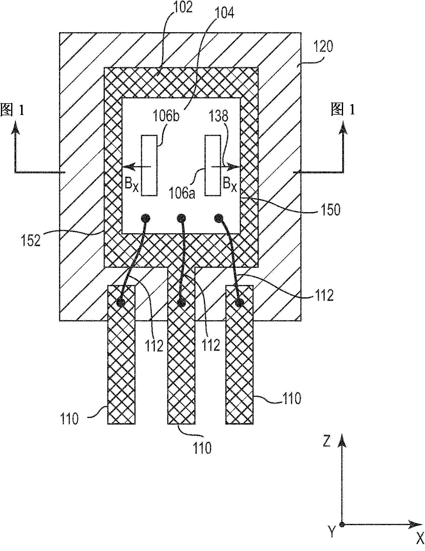
[0023] In the following detailed description, reference is made to the accompanying drawings, which form a part hereof, and in which are shown specific embodiments in which the invention may be practiced. In this regard, directional terms such as "top," "bottom," "front," "back," "front," "tail," etc. are used with reference to orientation in the figures being described. Because various components of the embodiments can be arranged in many different orientations, the directional terms are used for purposes of description and not for limitation. It is to be understood that other embodiments may be utilized and structural or logical changes may be made without departing from the scope of the present invention. Accordingly, the following detailed description is not intended to be limiting, and the scope of the invention is defined by the appended claims.

[0024] It should be understood that the features of the various exemplary embodiments described herein may be bonded to each...


PUM


Abstract

The present invention relates to a GMR sensor within molded magnetic material employing non-magnetic spacer, concretely to an integrated circuit including a leadframe, and a die having a top surface, a bottom surface, and a plurality of perimeter sides and including at least one magnetic field sensor element disposed proximate to the top surface, wherein the bottom surface is bonded to the leadframe. A molded magnetic material encapsulates the die and at least a portion of the leadframe, and provides a magnetic field substantially perpendicular to the top surface of the die. A non-magnetic material is disposed between the die and the molded magnetic material at least along perimeter sides of the die intersecting a lateral magnetic field component which is parallel to the top surface of the die.

Description

Background technique [0001] For example, magnetic field sensors such as magnetoresistive (XMR) sensors are used to detect wheel and / or or angular movement in various applications. For example, XMR sensors include anisotropic magnetoresistance (AMR) type sensors, tunneling magnetoresistance (TMR) sensors, giant magnetoresistance (GMR) type sensors, and super giant magnetoresistance (CMR) sensors. In particular, an XMR type magnetic field sensor comprises one or more sensor elements such as GMR sensor elements, wherein the sensor elements are formed as part of a semiconductor chip, wherein the semiconductor chip further comprises a integrated circuit. Thus, for example, a semiconductor chip is typically bonded to a carrier such as a copper lead frame to form a magnetic field sensor assembly. [0002] In the case of a speed and / or angle sensor, the assembly further includes a permanent magnet providing a reverse bias magnetic field for the XMR sensor element. The magnetic fie...

Claims


Application Information

Patent Timeline
Patent Type & Authority Applications(China)
IPC IPC(8): H01L43/10H01L43/02H01L43/12G01R33/09H10N50/01H10N50/80H10N52/00
CPCG01R33/093G01P3/488G01D5/24438B82Y25/00H01L43/02G01P1/026H01L2224/32245H01L2224/48091H01L2224/48257H01L2224/73265H10N50/80H01L2924/00014H01L2924/00
Inventor 克劳斯·伊利安阿道夫·科勒马丁·皮特兹乌韦·申德勒霍斯特·托伊斯
Owner INFINEON TECH AG
Features
  • R&D
  • Intellectual Property
  • Life Sciences
  • Materials
  • Tech Scout
  • Unparalleled Data Quality
  • Higher Quality Content
  • 60% Fewer Hallucinations
Learn More