Operating a synchronous motor having a permanent magnet rotor

A technology of synchronous motor and operation synchronization, applied in the direction of electronic commutation motor control, motor control, motor generator control, etc., can solve the problems of PMSM control difficulty and so on

Active Publication Date: 2011-08-03
BOMBARDIER TRANSPORTATION GMBH
View PDF3 Cites 7 Cited by
  • Summary
  • Abstract
  • Description
  • Claims
  • Application Information

AI Technical Summary

Problems solved by technology

On the other hand, as mentioned, if a fast response of the motor is required in dynamic situations, and if efficient use of resources (specifically available voltage and energy) is important, the control of PMSM is more difficult

Method used


Image

  • Operating a synchronous motor having a permanent magnet rotor
  • Operating a synchronous motor having a permanent magnet rotor
  • Operating a synchronous motor having a permanent magnet rotor

Examples


Embodiment Construction

[0053] The following example is for a motor in which the inductance of the stator electromagnet is not related to the current through the electromagnet. The given formula is therefore simpler than would otherwise be the case in practice.

[0054] Image 6 A permanent magnet synchronous motor 1 is shown schematically with a stator 3 and a rotor 5 . The magnetic flux of the stator 3 is generated, for example, by two magnetic coils 7 , 9 oriented perpendicularly to one another. The coil 7 is oriented in the direction of the coordinate axis α of the non-rotating coordinate system. The coil 9 is oriented in the direction of the other coordinate axis β of the non-rotating coordinate system.

[0055] The permanent magnets of the rotor 5 generate a magnetic flux oriented in the direction d of the rotating coordinate system whose rotational speed is the rotational speed of the rotor 5 . The other (orthogonal to d) coordinate axes of the rotating coordinate system are marked by "q"....


PUM


Abstract

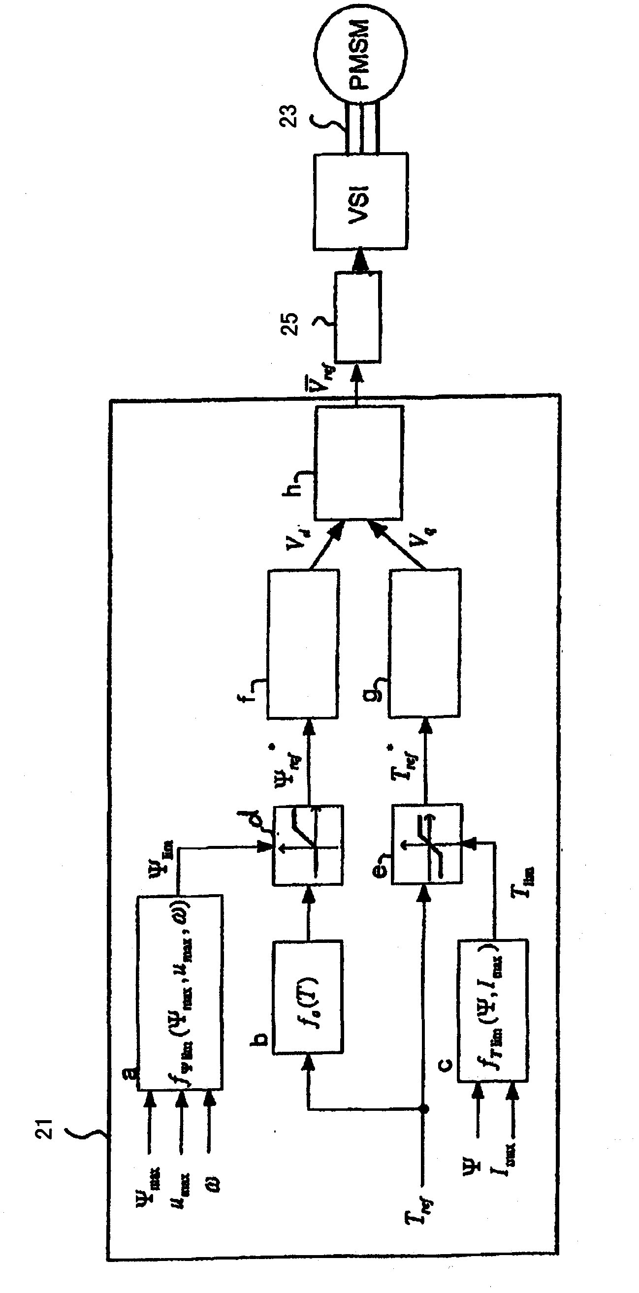
The invention relates to a method of operating a synchronous motor (1) having a stator comprising a set of electromagnets (7, 9) and having a permanent magnet rotor (5), wherein the synchronous motor (1) is controlled by calculating in a flux controller (f) a measure of a flux magnitude, which is the magnitude of the stator flux of the motor (1), and is controlled by calculating in a load angle controller (g) a measure of a load angle. Information about a desired motor torque or a reduced motor torque, which is smaller than the desired motor torque, is input to the load angle controller (g) and the load angle controller (g) calculates the measure of the load angle depending on the input motor torque. The measure of the flux magnitude is combined with the measure of the load angle to obtain commands for controlling electric currents of electromagnets of the stator, thereby directly controlling the stator flux. A flux limit value which depends on a predetermined maximum value of the stator flux allowed for the motor (1), which depends on a maximum value of an electric voltage, which is used to drive the currents through the stator electromagnets (7, 9), and which depends on the actual rotor speed is repeatedly calculated. During acceleration of the rotor (5) while the stator flux is smaller than the maximum flux allowed for the motor the measure of the flux magnitude is calculated depending on the output of a predetermined function, wherein the output of the predetermined function depends on the desired motor torque and corresponds to the magnitude of the stator flux, which results in the desired motor torque using the minimum possible stator current. The measure of the load angle is calculated depending on the desired motor torque.

Description

technical field [0001] The invention relates to a method of operating a synchronous motor having a stator comprising a set of electromagnets and having a permanent magnet rotor. This motor is commonly referred to as a permanent magnet synchronous motor (PMSM). The invention also relates to a device for operating the electric motor. A particular area of ​​interest is the control of PMSMs, which are the propulsion motors of rail vehicles. Background technique [0002] Typically, asynchronous electric motors with a rotor with at least one electromagnet are used for propulsion of rail vehicles. The term "rail vehicle" includes any trajectory-constrained vehicle. These asynchronous motors can be easily controlled since not only the electromagnets of the stator but also single or multiple electromagnets of the rotor can be adapted to the desired operating behavior. However, PMSM motors have some advantages. In particular, the power density (power available per volume) is high...

Claims


Application Information

Patent Timeline
Patent Type & Authority Applications(China)
IPC IPC(8): H02P21/12
CPCH02P21/0089H02P21/12H02P21/0046H02P2207/05H02P21/00H02P21/28
Inventor J·加利奇
Owner BOMBARDIER TRANSPORTATION GMBH
Why Eureka
Try Eureka