Chamfering device for hard and brittle plates

A technology of hard and brittle plates and chamfering devices, which is applied to the parts of grinding machine tools, the control of workpiece feed motion, and the machine tools suitable for grinding the edge of workpieces, etc. It can solve the problems of reducing productivity and obtaining the edge, etc. problem, to achieve the effect of high productivity and high precision chamfering processing

Inactive Publication Date: 2016-03-16
NAKAMURATOME SEIMITSU IND
View PDF9 Cites 0 Cited by
  • Summary
  • Abstract
  • Description
  • Claims
  • Application Information

AI Technical Summary

Problems solved by technology

[0022] However, when the required processing accuracy becomes stricter, it is difficult to obtain the edge. Ultimately, it is necessary to measure the processing dimensions of all workpieces after processing, and change the correction value at any time as needed. In the chamfering device of the existing structure have to reduce productivity

Method used


Image

  • Chamfering device for hard and brittle plates
  • Chamfering device for hard and brittle plates
  • Chamfering device for hard and brittle plates

Examples


Embodiment Construction

[0042] Hereinafter, several preferred embodiments of the present invention will be described with reference to the drawings.

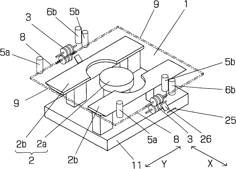
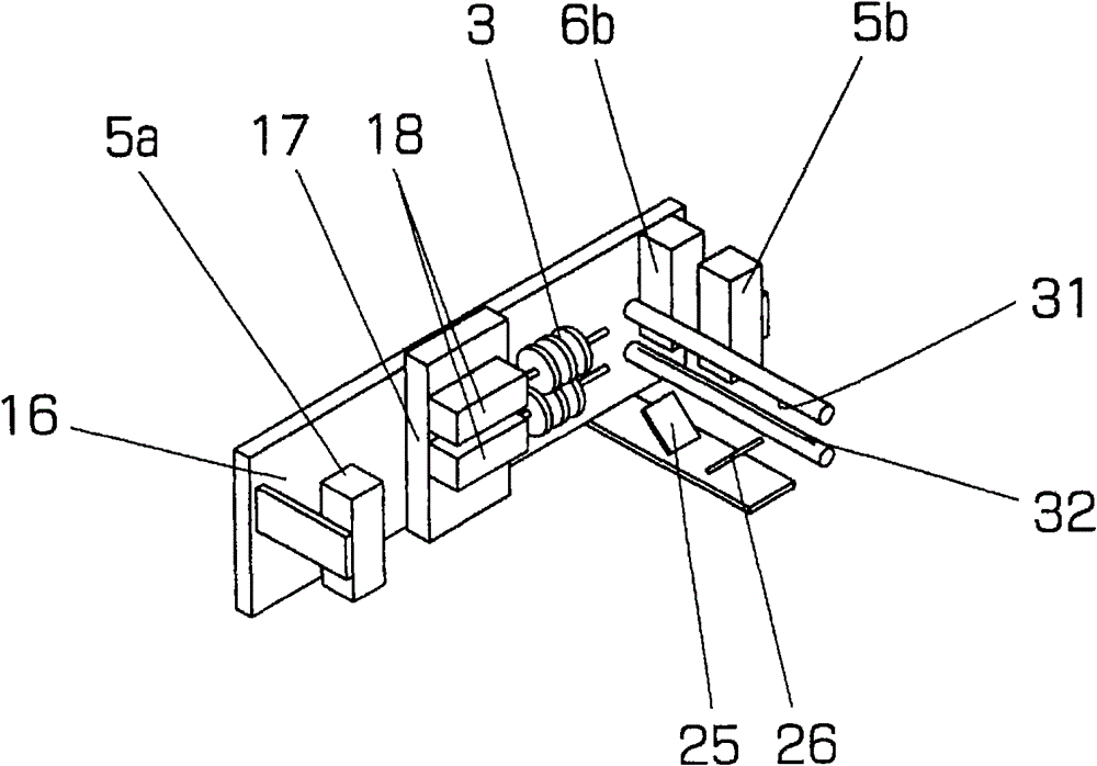
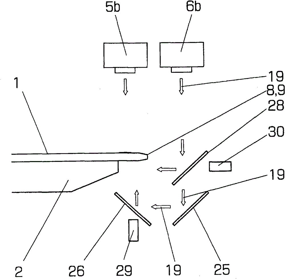
[0043] Figure 1 ~ Figure 3 It is a figure showing the first embodiment of the chamfering device of the present invention, figure 1 It is a perspective view showing the outline of the main machine structure, figure 2 is a schematic perspective view showing the installation structure of the tool and the camera, image 3 It is a front view showing the positional relationship between the downstream camera and the workpiece.

[0044] In the figure, 11 represents the workbench that moves along the guide rail in the y direction not shown, 2a represents the round table installed on the workbench 11 through the rotation device that is not shown in the figure and rotates around the vertical axis, and 2b represents the round table installed on the table The elongated side tables along the feed direction on both sides of the width direction (X direction in t...


PUM


Abstract

The invention provides a chamfering device of a hard fragile plate, which is used for processing a glass base plate used for a display panel and edges of other hard fragile plates. The chamfering device can measure the processing dimensions of all processed workpieces completely without or hardly increasing production beats, thereby being capable of realizing higher processing accuracy without reducing the processing accuracy. In the chamfering device comprises upstream side upper video cameras, a downstream side upper video camera and a downstream side lower camera, wherein the upstream side upper video cameras for observing the upper surfaces of the two side edge parts of workpieces are configured at both sides of the width direction of a work table, which are opposite to the upstream side of the feed direction of a tool; the downstream side upper video camera for observing the upper surfaces of the two side edge parts of the workpieces is arranged at the downstream side of the feed direction of the work table of the tool; and the downstream side lower camera for observing the lower surfaces of the two side edge parts of the workpieces is arranged at the downstream side. By means of the chamfering device, chamfering processing is carried out when the work table is in feed motion, and the chamfering dimension is measured by utilizing the downstream side cameras after the chamfering processing is carried out.

Description

technical field [0001] The present invention relates to a chamfering device for processing the edges of rectangular glass substrates and other hard and brittle plates used in display panels and the like. In particular, the present invention relates to the above-mentioned device capable of measuring processing dimensions in order to accurately set the angle of a table on which a hard and brittle plate is placed and the position of a processing tool. Background technique [0002] The chamfering device of the glass substrate (hereinafter referred to as "substrate" or "workpiece") uses a tool (generally a grinding wheel) to chamfer and Device for rounding. Generally, such as Figure 8 As shown, this chamfering device has a workbench 2 that absorbs a substrate 1 by negative pressure, and tools 3 arranged on both sides of the workbench. The table 2 can be rotated 90 degrees around a vertical axis by a rotation device not shown. The table 2 and the tool 3 are relatively movable ...

Claims


Application Information

Patent Timeline
Patent Type & Authority Patents(China)
IPC IPC(8): B24B9/08B24B49/03
Inventor 小幡智昭
Owner NAKAMURATOME SEIMITSU IND
Why Eureka
Try Eureka