Ink-jet recording device and recording method

An inkjet recording method and inkjet recording technology, which are applied in the direction of inking devices, printing devices, printing, etc., can solve problems such as deterioration of image quality, difficulty in repairing, and reduction in production efficiency of printing systems, so as to prevent the decline in image quality Effect

Inactive Publication Date: 2007-03-21
FUJIFILM CORP
View PDF8 Cites 0 Cited by
  • Summary
  • Abstract
  • Description
  • Claims
  • Application Information

AI Technical Summary

Problems solved by technology

However, in this case, when high-speed printing is performed with high precision, high-precision control is required, which is technically difficult
In addition, when a borderless print head is used, the number of nozzles is huge, and there will be problems with the print head due to failures such as nozzle clogging and collapse, and the quality of the image will deteriorate accordingly
When a nozzle misfiring occurs, the problem is very difficult to fix, requiring the printhead itself to be replaced, reducing the productivity of the printing system to zero before the replacement is complete

Method used


Image

  • Ink-jet recording device and recording method
  • Ink-jet recording device and recording method
  • Ink-jet recording device and recording method

Examples


example 1

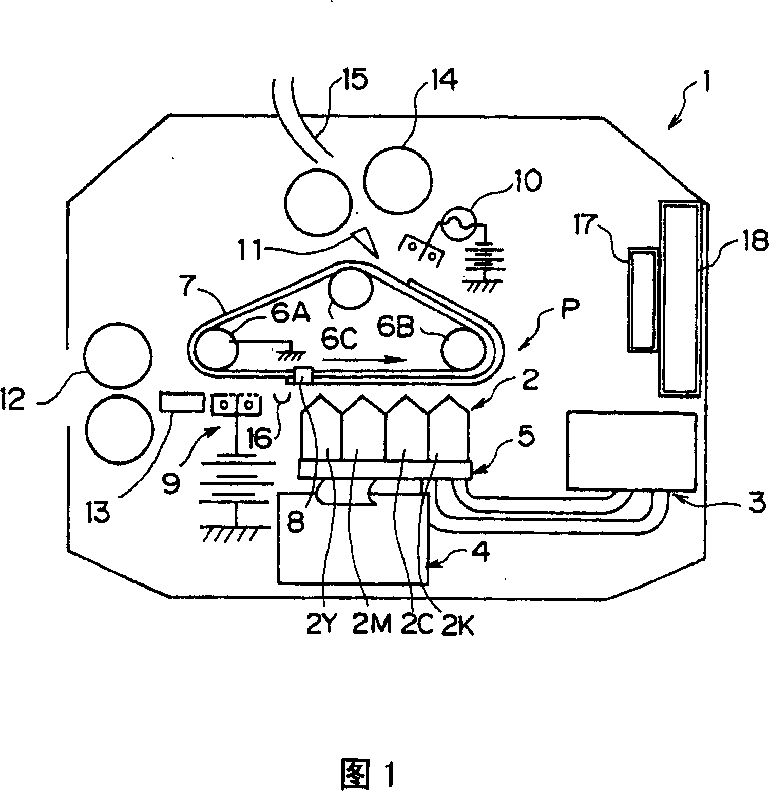
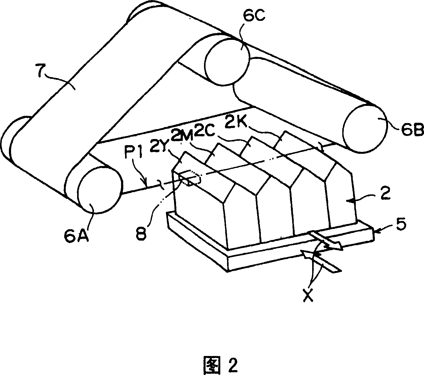
[0140] In an ink jet recording apparatus shown in FIG. 1, ink tanks to which four independent ink jet heads are connected are filled with four kinds of inks. (For ink, positively charged color particles with an average diameter of 0.7 to 1.0 μm are dispersed in ISOPAR G. Carbon black, phthalocyanine dye, CI red pigment, CI yellow pigment can all be used as pigments for color particles. ) A 150dpi, 833-channel head shown in Figure 9 (the channels are arranged in 3 staggered rows at a density of 50dpi) was used as an inkjet head, and a silicone rubber heating roller containing a 1kW heater was used As a fixing element. The ink tank is equipped with an immersion heater and a stirring impeller as ink temperature control elements. The temperature of the ink was set at 30 °C, the stirring impeller was rotated at 30 rpm, and the temperature was controlled by a thermostat. Stirring impellers are used as stirring elements to prevent settling and coagulation. The ink channel is made ...

example 2

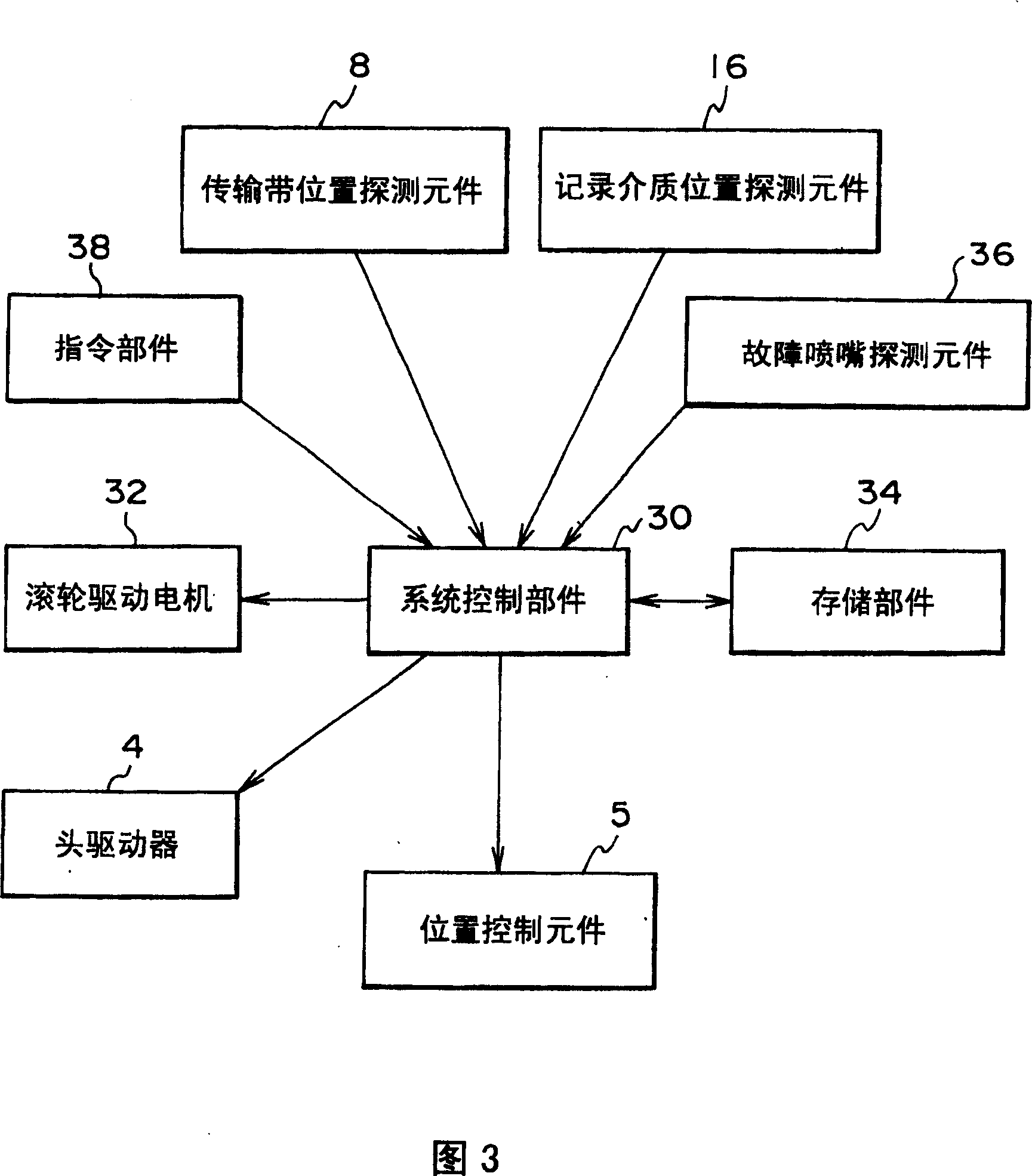
[0144]In the inkjet recording apparatus shown in FIG. 7, the 200 dpi head with 601 channels (arranged in four staggered rows with a channel density of 50 dpi) shown in FIG. 11 was employed as the inkjet head. A heating roller made of Teflon (R)-coated silicone rubber with a heater of 0.8 kW thereon was used as a fixing member. Belts made of a metal strip bonded together with polyimide film were used as conveyor belts. The end of the belt is optically interpreted by the conveyor position sensing element and the position control element is driven to image at 1800dpi. The other conditions of imaging were the same as those in Example 1. Imaging problems due to dust, etc. are not visible at all, nor is image quality degradation due to problems such as changes in ink dot diameter caused by drastic temperature changes and increased printing times. Therefore, high-quality printing can be achieved, and the obtained printed documents have extremely clear images free from linear uneven...

example 3

[0146] In the device of FIG. 8, the 1200dpi, 10-inch wide full-line head-type channel printhead shown in FIG. 23 is used. Other condition settings for imaging were the same as in Example 1. Imaging problems are virtually invisible, as are image quality degradations due to issues such as drastic temperature changes and dot diameter changes as the number of copies printed increases. Therefore, full-color printing on one side and two sides can be realized.

[0147] After printing is complete, the ISOPAR G on the printhead is cycled to perform cleaning, and further cleaning can be performed by contacting the distal end of the printhead with a non-fibrous cloth containing ISOPAR G. In this way, after three months, good printed material can be produced without any maintenance operations. In addition, when a nozzle fails to eject ink, it is interpolated by other nozzles using the previously described method without performing elaborate cleaning. As a result of using adjacent nozzl...


PUM


Abstract

An inkjet recording device and inkjet recording method capable of forming a high quality image with a simple structure. A transport belt position detection component detects a position of an end portion of a transport belt and outputs the detected position to a system control section. A recording medium position detection component detects a position of an end portion of a recording medium and outputs the detected position to the system control section. A position control component is capable of moving on the basis of instructions from the system control section for movement across a transport direction.

Description

technical field [0001] The present invention relates to an inkjet recording apparatus and an inkjet recording method. Background technique [0002] As far as forming a print image on a print medium based on an image data signal, there are electrophotographic technology, sublimation type and fusion type thermal transfer technology, inkjet technology, and the like. Electrophotography requires the process of forming an electrostatic latent image, which is achieved by exposing a photosensitive drum to a static charge. The system is thus complicated and the equipment is expensive. Using thermal transfer technology is inexpensive equipment, but because of the ink ribbon, running costs are high and waste is generated. In contrast, with inkjet technology, printing is directly achieved on a recording medium by jetting ink only to the portion to be imaged with inexpensive equipment. As a result, colorants are used efficiently and the operating costs are cheap. [0003] For printin...

Claims


Application Information

Patent Timeline
Patent Type & Authority Patents(China)
IPC IPC(8): B41J2/06B41J2/01B41J11/00
CPCB41J11/007B41J2202/12B41J11/008
Inventor 中沢雄祐古川弘司
Owner FUJIFILM CORP
Why Eureka
Try Eureka