
Motor vehicle forward structure

A car body and front end technology, which is applied in the front end of the car body, can solve problems such as hindering cooling air and reducing cooling efficiency of coolers, and achieve the effects of improving mechanical stability, improving compatibility, and large degrees of freedom

Inactive Publication Date: 2011-08-10
GM GLOBAL TECH OPERATIONS LLC
View PDF4 Cites 2 Cited by
  • Summary
  • Abstract
  • Description
  • Claims
  • Application Information

AI Technical Summary

Problems solved by technology

A disadvantage of the bumper cross member 9 according to the prior art, which connects the crash boxes 4 and 5 and thus the vehicle side members 2 and 3 , is that the continuous bumper cross member 9 hinders the flow of cooling air to the front end of the vehicle, and Reduced cooling efficiency on coolers arranged behind the bumper cross member 9 in the direction of travel

Method used


Image

  • Motor vehicle forward structure
  • Motor vehicle forward structure
  • Motor vehicle forward structure

Examples


Embodiment Construction

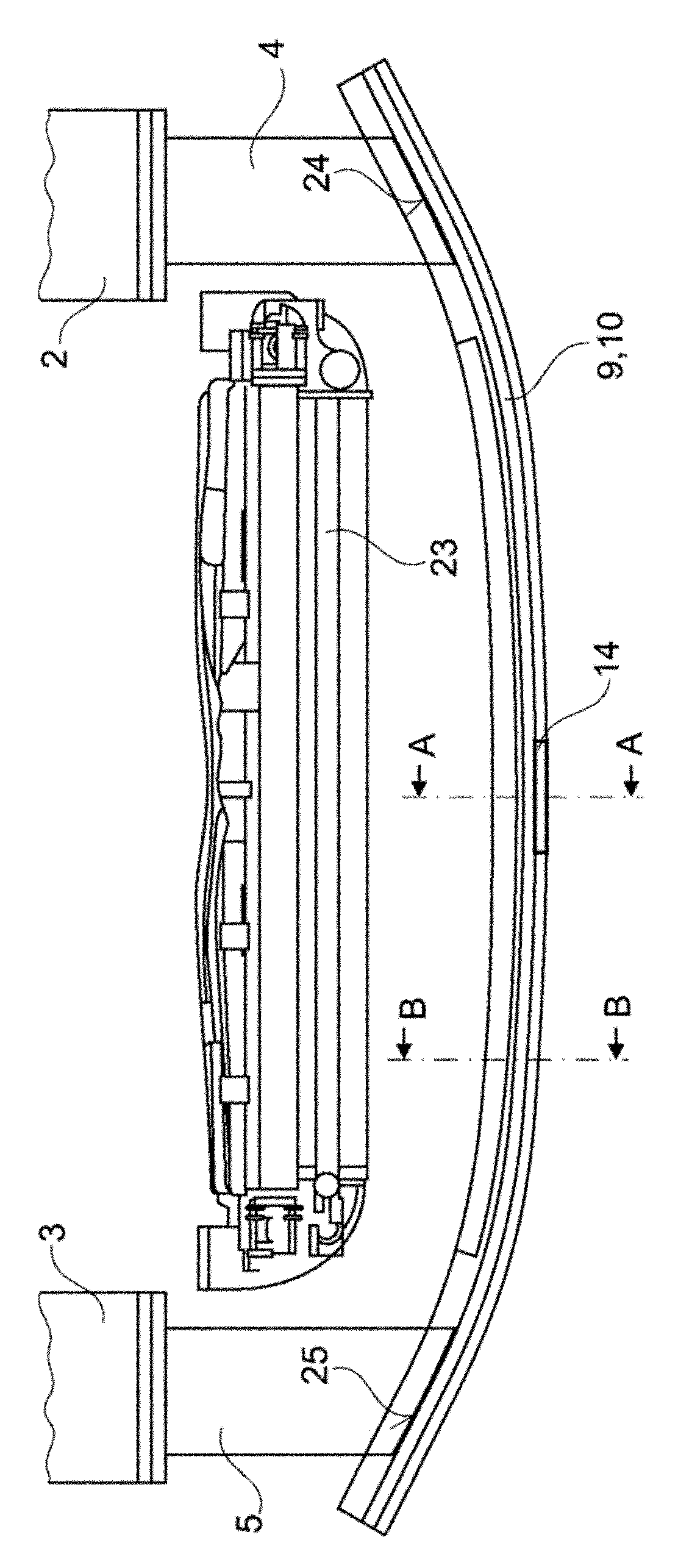
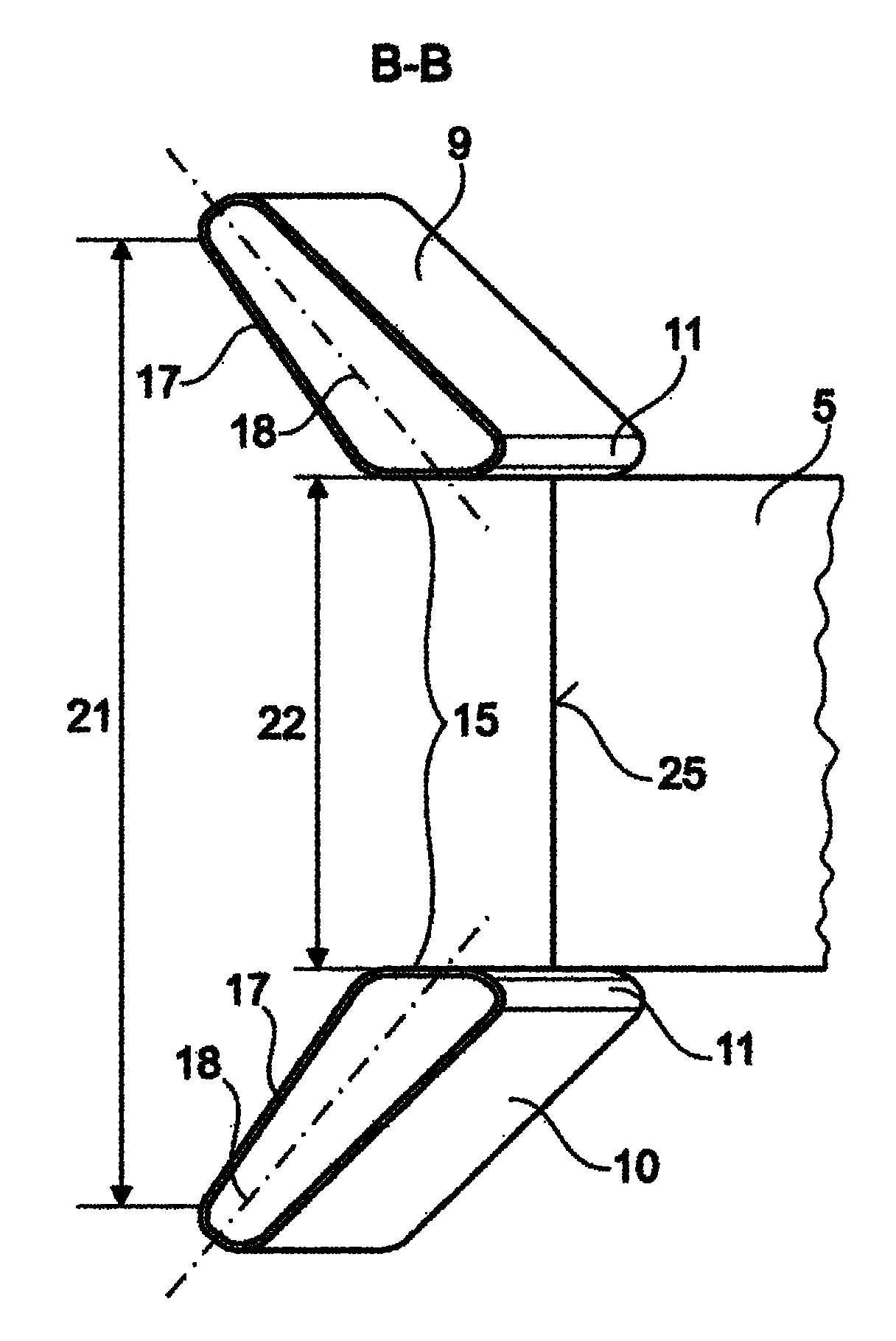
[0020] figure 1 A schematic front view of a motor vehicle front end 1 according to an embodiment of the invention is shown. For this reason, only so-called frontal crash structures for meeting crash and cooling requirements are shown for the motor vehicle front end 1 . All other front end components such as shock absorber diaphragms, cooling air louvers and other configurations are omitted here. figure 1 The schematic front view shown in , only shows the cross member structure 8 designed as a crash structure or bumper structure. Contrary to the previously shown prior art, the cross member structure 8 consists of a first upper bumper cross member 9 and a second lower bumper cross member 10 , which are fastened in their end regions 11 and 12 respectively in the crash zone. box of 4 or 5 on. Such fixing may include welding, brazing or bolting. The crash box itself has a flexible material that deforms and attenuates the crash energy when subjected to a crash or impact energy...


PUM


Abstract

The invention relates to a motor vehicle forward structure (1), comprising at least two vehicle chassis beams (2, 3), at least two crash boxes (4, 5) which are arranged at the front ends (6, 7) of the vehicle chassis beams (2, 3), and at least one transverse beam structure (8) which is secured to the crash boxes(4, 5). The transverse beam structure (8) is provided with two transverse bumper carriers (9, 10) with a first transverse bumper carrier (9) being disposed above the crash boxes (4, 5) and a second transverse bumper carrier (10) being disposed below the crash boxes. The crash boxes (4, 5) are fixed in a left and right end area (11, 12) of the transverse beam structure (8) between the transverse bumper carriers and at the ends (6, 7) of the vehicle chassis beams (2, 3).

Description

technical field [0001] The invention relates to a front end of a motor vehicle body comprising at least two side members and at least two crash boxes arranged on the front end of the side members, as well as at least one cross member structure connected to the crash boxes. Background technique [0002] This type of beam structure, which transfers the crash energy to the crash box as an energy absorber, is used in automobiles to increase safety. Furthermore, damage to the vehicle body structure in the event of an accident at low speeds can be kept to a minimum by using such a cross member structure in conjunction with a crash box. For this purpose, the crash box is designed as a deformation body which is installed in the motor vehicle in such a way that when the vehicle hits an obstacle, the deformation body absorbs the resulting crash energy via the cross member structure and partly absorbs the crash energy through its deformation. As a result, the crash box reduces the tra...

Claims


Application Information

Patent Timeline
IPC IPC(8): B60R19/34B60R19/04B60K11/06
CPCB60K11/02B60R19/34B60R2019/486B60R19/48B60R19/24B60R19/12
Inventor 斯坦尼斯劳·克利梅克
Owner GM GLOBAL TECH OPERATIONS LLC
Learn More