Detecting method and device for failure of automatic air brake system of train

A technology for air braking and detecting trains, which is applied in the direction of braking safety systems, etc., and can solve problems such as the influence of modeling accuracy and the influence of device detection accuracy

Active Publication Date: 2011-08-10
LOCOMOTIVE & CAR RES INST OF CHINA ACAD OF RAILWAY SCI
View PDF6 Cites 41 Cited by
  • Summary
  • Abstract
  • Description
  • Claims
  • Application Information

AI Technical Summary

Problems solved by technology

Due to the existence of leakage in the train pipe and gas circuit, the accuracy of

Method used


Image

  • Detecting method and device for failure of automatic air brake system of train
  • Detecting method and device for failure of automatic air brake system of train
  • Detecting method and device for failure of automatic air brake system of train

Examples


Embodiment 1

[0072] Image 6 It is a flow chart of an embodiment of the method for detecting the failure of the automatic air brake system of the train according to the present invention. see Image 6 , the method includes the following steps:

[0073] S101, receiving and storing the train pipe pressure and the brake cylinder pressure collected during the sampling period transmitted by the sensor.

[0074] In the present invention, two types of pressure sensors are installed in the train braking system, that is, the train pipe pressure sensor and the brake cylinder pressure sensor. The train pipe pressure sensor is installed on the pipeline between the cut-off plug and the distribution valve to collect the train pipe pressure. The brake cylinder pressure sensor is installed on the pipeline between the brake cylinder relief plug and the anti-skid exhaust valve to collect the pressure of the brake cylinder. The pressure of these two measuring points reflects the input and output characte...

Embodiment approach

[0082] Wherein, an implementation manner of judging whether the braking system is in a normal working state is as follows:

[0083] Calculate the decompression speed of the train pipe in the time interval from the time before a certain multiple of the sampling period to the time of the sampling period. For example, subtracting the pressure of the first train pipe from the pressure of the second train pipe and then dividing it by the time between collecting the pressures of the two train pipes, the decompression speed of the train pipe within the time interval can be obtained.

[0084] Comparing the decompression speed of the train tube with the set first decompression speed threshold;

[0085] When it is judged that the decompression speed is greater than the first decompression speed threshold, it is further judged whether the decompression speed is greater than the set second decompression speed threshold, if the decompression speed is greater than the second decompression s...

Embodiment 2

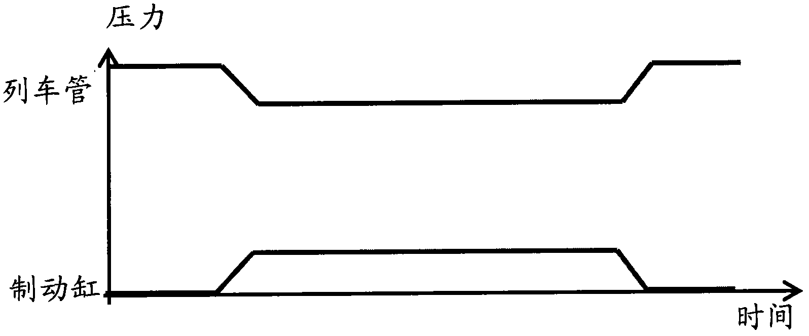
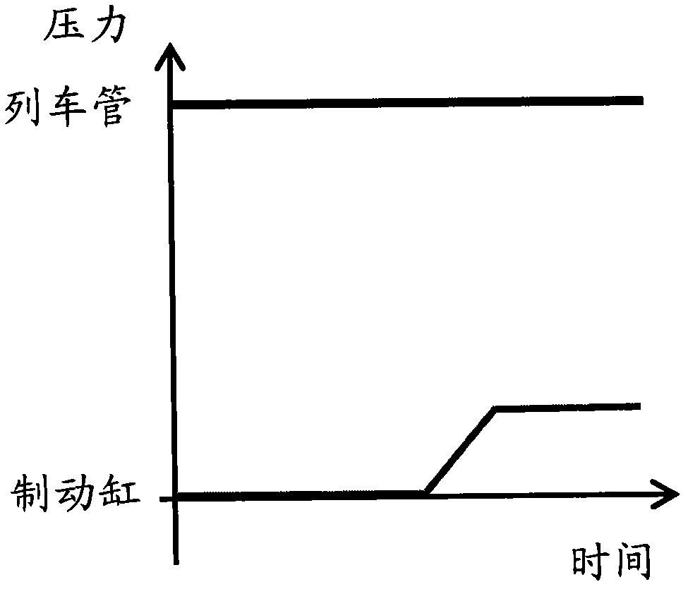
[0089] In the embodiment of the present invention, the inventor combines Figure 1 to Figure 5 Analysis of the characteristics of each fault further gives a table of fault detection conditions, see Table 1. When the train pipe pressure and brake cylinder pressure meet one of the following detection conditions, the brake system has a fault corresponding to the detection condition.

[0090] Table 1

[0091] fault name

Detection conditions

natural braking

r=0 and Pz=0 change to Pz>0

severe natural braking

∫PzVdt>M and Pz>50kPa during natural braking

natural relief

r>0 and Pz>0 change to Pz=0

No braking effect

r>0 and Pz=0

Poor relief

r>0 changes to r=0 while Pz>0

severe poor response

When the relief effect is poor, ∫PzVdt>M and Pz>50kPa

brake off

Pz=0 and r=600

[0092] Among them: M is the heat capacity of the brake disc (refer to the data provided by the brake disc manufacturer of t...


PUM


Abstract

The invention relates to a detecting method for the failure of an automatic air brake system of a train, which comprises the following steps of: receiving and storing a train pipe pressure and a brake cylinder pressure transmitted by a sensor and acquired in a sampling period; obtaining first train pipe pressure and first brake cylinder pressure acquired in the sampling period as well as second train pipe pressure and second brake cylinder pressure acquired before a certain times of the sampling period; and judging whether the brake system is in failure according to the change of the first train pipe pressure relative to the second train pipe pressure and according to the change of the first brake cylinder pressure to the second brake cylinder pressure, wherein failure prompting information is output when the brake system is judged to be in failure. Correspondingly, the invention also relates to a detecting device for the failure of an automatic air brake system of a train, and monitoring and alarming equipment for the braking of the train. When the detecting method, the detecting device and the monitoring and alarming equipment are adopted, the online detection on the failure of the automatic air brake system of the train can be realized in real time, and the reliability and the accuracy of the detection result can reach a higher level.

Description

technical field [0001] The invention relates to the technical field of train braking, in particular to a method and device for detecting faults in a train automatic air braking system, and to a train braking monitoring and alarming device. Background technique [0002] On the one hand, the braking system of the railway train is to slow down or stop the train under any circumstances to ensure the safety of the train; on the other hand, it is also an important means to increase the running speed of the train and increase the traction weight, that is, to improve the railway transportation capacity. The braking force generated by the train braking system is a human-induced resistance that can be controlled and adjusted by the driver. It is an external force that prevents the train from running due to the wheel-rail adhesion generated by the locomotive and vehicle braking devices. However, train brake system failures often occur during driving. With the increase of train speed, b...

Claims


Application Information

Patent Timeline
IPC IPC(8): B60T17/18
Inventor 王旭如裘立红赵玉其
Owner LOCOMOTIVE & CAR RES INST OF CHINA ACAD OF RAILWAY SCI
Why Eureka
Try Eureka