Rear beam driving mechanism of jet loom

A back beam drive mechanism, air-jet loom technology, applied in looms, textiles, textiles and papermaking, etc., can solve the problems of air-jet looms, severe vibration of the back beam, etc., and achieve the effect of reducing the breakage rate and high production efficiency

Inactive Publication Date: 2011-08-10
JIANGSU WANGONG TECH GRP CO LTD
View PDF7 Cites 5 Cited by
  • Summary
  • Abstract
  • Description
  • Claims
  • Application Information

AI Technical Summary

Problems solved by technology

[0002] The air-jet loom uses jet air to pull the weft yarn through the shed, and all the warp yarns bypass the surface of the back beam. Although the back beam drive mechanism with a loom speed of 100-200 rpm is still in use, the commonly used air jet loom is now The speed of the loom is generally 900-1000 rpm. Under high-speed operation, the swing frequency of the back beam reaches above 15Hz. During the high-speed weaving process of the air-jet loom, the back beam vibrates violently. The form obviously cannot meet the needs of the air-jet loom

Method used


Image

  • Rear beam driving mechanism of jet loom
  • Rear beam driving mechanism of jet loom
  • Rear beam driving mechanism of jet loom

Examples


Embodiment Construction

[0013] The preferred embodiments of the present invention will be described in detail below in conjunction with the accompanying drawings, so that the advantages and features of the present invention can be more easily understood by those skilled in the art, so as to define the protection scope of the present invention more clearly.

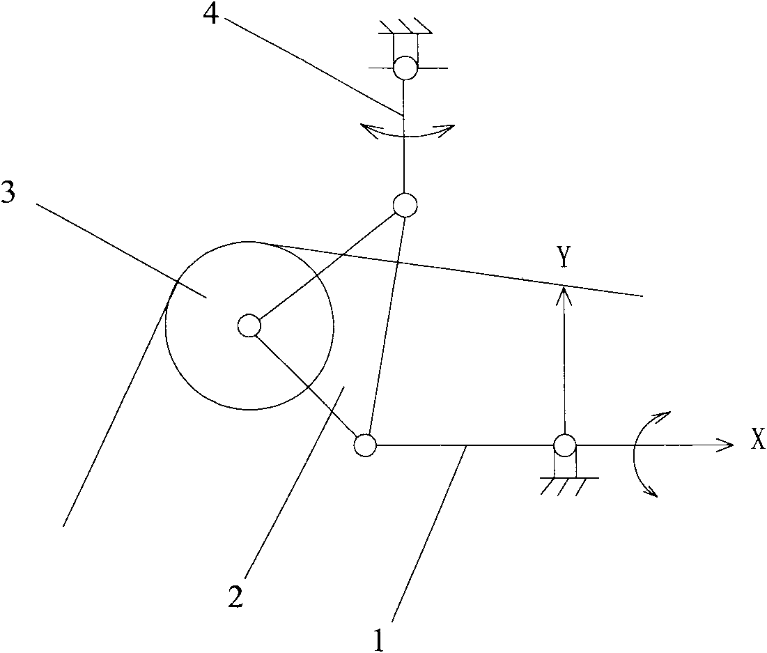
[0014] figure 1 Shown is the back rest driving mechanism in the prior art, which is a double rocker mechanism. All the warp yarns bypass the surface of the back rest 3. During the high-speed weaving process, the back rest vibrates greatly and the force on the rods is large, which increases the load on the warp yarns. As the warp tension increases, the rate of warp yarn breakage increases significantly, and if the warp yarn breakage is too frequent, the superiority of the high-speed loom will be offset.

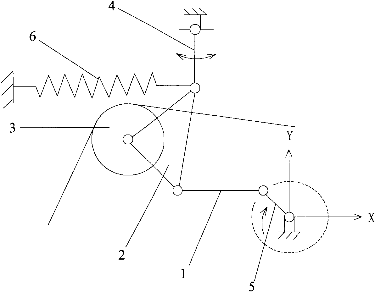
[0015] refer to figure 2 , the back beam driving mechanism of the air-jet loom of the present invention is a kind of five-bar mechanism, and i...


PUM


Abstract

The invention provides a rear beam driving mechanism of a jet loom. The rear beam driving mechanism comprises a crank with adjustable length, a connecting rod, a swing block, a swing arm and a rear beam, wherein a motor supplies rotating power to the crank, one end of the connecting rod is hinged with the end of the crank, the swing block is hinged with the other end of the connecting rod, and one end of the swing arm is hinged with the swing block; the swing block is hinged with the rear beam; the positions where the swing block is hinged with the rear beam, the connecting block and the swing arm respectively are not superposed; the other end of the swing arm is hinged on an external fixed object; a spring is connected between the swing arm and the external fixed object; and the spring provides a reset force for the swing arm. The rear beam driving mechanism has two degrees of freedom, namely warps pull the rear beam and the motor drags the crank; and by structural style improvement of the mechanism, the state of warp tension is controlled more finely, the end breakage rate of the warps can be reduced, and the work efficiency is improved.

Description

technical field [0001] The invention relates to a driving device, in particular to a back rest driving mechanism used on an air-jet loom. Background technique [0002] The air-jet loom uses jet air to pull the weft yarn through the shed, and all the warp yarns bypass the surface of the back beam. Although the back beam drive mechanism with a loom speed of 100-200 rpm is still in use, the commonly used air jet loom is now The speed of the loom is generally 900-1000 rpm. Under high-speed operation, the swing frequency of the back beam reaches above 15Hz. During the high-speed weaving process of the air-jet loom, the back beam vibrates violently. The form obviously cannot meet the needs of the air-jet loom. [0003] The main obstacle to the development of air-jet looms to higher operating speeds is the limited ability of the warp yarns to withstand the speed. The high-speed operation of the loom increases the load on the warp yarns. When the loom speed increases, the tension o...

Claims


Application Information

Patent Timeline
Patent Type & Authority Applications(China)
IPC IPC(8): D03D49/22D03D49/12D03D47/30
Inventor 祝章琛
Owner JIANGSU WANGONG TECH GRP CO LTD
Why Eureka
Try Eureka