
PVC (Polyvinyl Chloride) latch floor board

A floor and lock technology, which is applied in the direction of floors, buildings, building structures, etc., can solve problems such as seams and lock floor connection failures

Inactive Publication Date: 2011-08-10
葛跃进
View PDF5 Cites 2 Cited by
  • Summary
  • Abstract
  • Description
  • Claims
  • Application Information

AI Technical Summary

Problems solved by technology

And because the size of the connection parts of these floor boards is usually very small, when it is used for PVC lock floor, it is very easy to produce seam phenomenon, so that the connection between the lock floors fails.

Method used


Image

  • PVC (Polyvinyl Chloride) latch floor board
  • PVC (Polyvinyl Chloride) latch floor board
  • PVC (Polyvinyl Chloride) latch floor board

Examples


Embodiment 1)

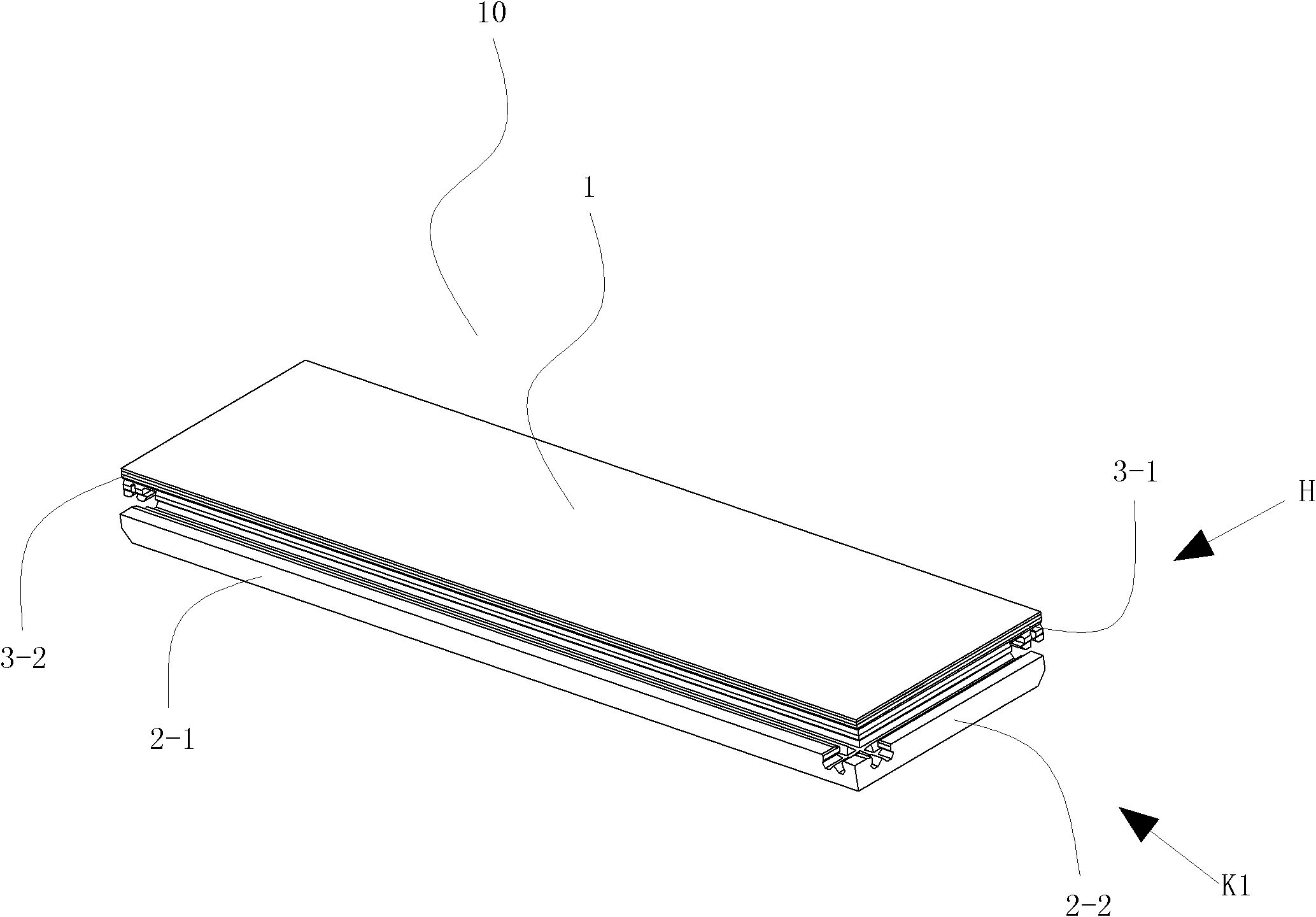
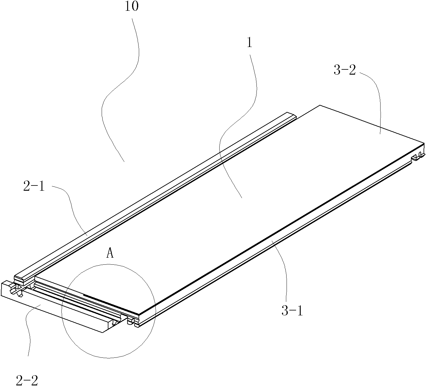
[0079] The description orientation of this embodiment is according to figure 1 The up, down, left, and right directions shown are described, that is, the width direction of the floor is the left and right direction, the thickness direction of the floor is the up and down direction, and the length direction of the floor is the front and rear direction (ie figure 1 The lower left is the front side, figure 1 The upper right is the rear side), the direction close to the center of the floor is called the inner side, and the direction away from the center of the floor is called the outer side. The two-dot dash line in the figure is a schematic boundary line between each part.

[0080] See figure 1 and Figure 4 , the PVC locking floor 10 of this embodiment includes a floor body 10-1, a decorative pattern 10-2-1 and a transparent wear-resistant layer 10-2-2; the decorative pattern layer 10-2-1 is fully covered and fused to the floor body On the upper surface of 10-1, the tran...

Embodiment 2)

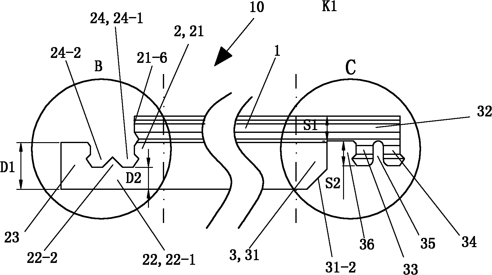
[0108] The rest of this embodiment is the same as that of Embodiment 1, except that the inner lower part of the inner tongue 33 of the elastic double tongue portion is provided with a bow-shaped inner convex portion 33-1 with a cross-sectional shape that protrudes inward (see Figure 15 ). The inner-outward distance L3 of the inner convex portion 33 - 1 is 0.24 to 1 mm (0.3 mm in this embodiment). The outer lower part of the outer tongue 34 is provided with a bow-shaped outer convex part 34-1 with a cross-sectional shape facing inwardly (see Figure 15 ). The outward-inward distance L4 of the convex portion 34 - 1 is 0.24 to 1 mm (0.3 mm in this embodiment).

[0109] See Figure 14 The cross-sectional shape of the inner tongue limiting groove 24-2-1 of the lock main groove 24 of the groove seat part 2 is an opening corresponding to the cross-sectional shape of the inner tongue 33 of the elastic double tongue part 3. Bows facing inward. The cross-sectional shape of the out...


PUM

PropertyMeasurementUnit
thicknessaaaaaaaaaa
lengthaaaaaaaaaa
lengthaaaaaaaaaa

Abstract

The invention relates to a PVC (Polyvinyl Chloride) latch floor board which comprises a main body part, slot seat parts and corresponding elastic double-tongue parts; the main body part is a quadrilateral prism body, wherein the shape of the upper surface of the main body part corresponds to the quadrilateral shape of a walking face of the PVC latch floor board; each slot seat part of the PVC latch floor board is a part which can be mutually latched and connected with the adjacent and corresponding elastic double-tongue part of the PVC latch floor board from the lower side when the PVC latch floor board is used; and each elastic double-tongue part of the PVC latch floor board is a part which can be mutually latched and connected with the adjacent and corresponding slot seat part of the PVC latch board when the elastic double-tongue part is used. When the PVC latch floor board is used, mutually contacted limits in four directions are arranged between every two adjacent PVC latch floor boards so that the PVC latch floor boards are firmer to latch and not easy to fall off. When the PVC latch floor board is paved, the active pavement of one PVC latch floor board to a plurality of PVC latch floor boards can be finished just by applying an action force in one direction to the paved floor boards, and thus simple, convenient and rapid effects can be achieved.

Description

technical field [0001] The invention relates to a PVC locking floor. Background technique [0002] PVC lock floor is polyvinyl chloride lock floor. As a building decoration material, it has been widely used in homes and various public places. From the perspective of environmental protection and easy installation, when laying the floor system, the distance between the floors Glue is basically not used for interconnection, and the concave and convex parts arranged on the tenon and tenon parts are used to lock and fix each other. [0003] The size of the tenon and tenon groove on the usual locking floor is relatively small (generally no more than 3 mm), so the precision requirements for the tenon and tenon groove are relatively high, and the quality of the cooperation between the tenon and the tenon groove determines The quality of floor laying. Take the laying of existing rectangular solid wood lock floor (hereinafter referred to as lock floor) on the floor of a rectangular ...

Claims


Application Information

Patent Timeline
Patent Type & Authority Applications(China)
IPC IPC(8): E04F15/10
Inventor 葛跃进
Owner 葛跃进
Learn More